FUNCTION
Sensing common
-Remote sense
-Output
Common
25
V
ac winding
+26
V
dc
Collector lead of pnp series pass
Transformer shield
Ground
-26
V
dc
Collector lead of npn series pass
PWR
18
V
ac
winding
Ground
Ground
+8
Vdc
25
V
ac winding
Floating
Supply
Board
CONTACTS CONTACTS
2884
278-
2684
25B*
2484
23B4
228
+
21B*
20B-
198-
18B-w
17B-w
16B-
15B-
14B+
1384
12B+#
11B+
10B-k
9B-
8B4
78-
6B4
5B-
4B
-ti
3B-h
28
*
IBu
Bot
FUNCTION
Sensing common
+Remote sense
+Output
Common
Family Key
25
V
ac winding
+26
V
dc
Base lead of pnp series pass
Emitter lead of pnp series pass
Ground
-26
V
dc
Emitter lead of npn series pass
TM
5000
Key
Base lead of npn series pass
18
V
ac
winding
Ground
Ground
+8 Vdc
25
V ac winding
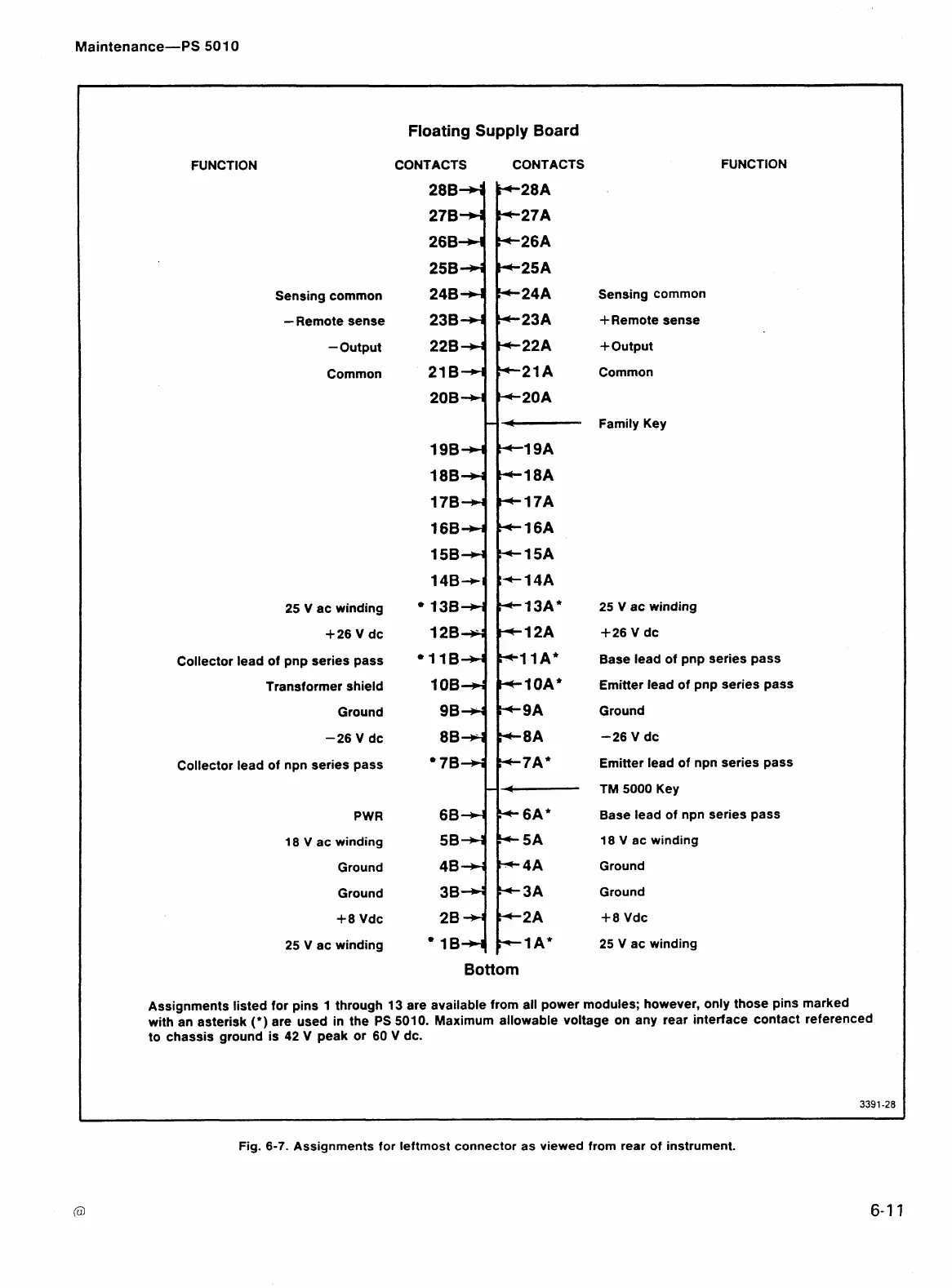
Assignments listed for pins
1
through
13
are available from all power modules; however, only those pins marked
with an asterisk
(')
are used in the PS
5010.
Maximum allowable voltage on any rear interface contact referenced
to chassis ground is
42
V
peak or 60
V
dc.
Fig.
6-7.
Assignments for leftmost connector
as
viewed from rear of instrument.
 Loading...


