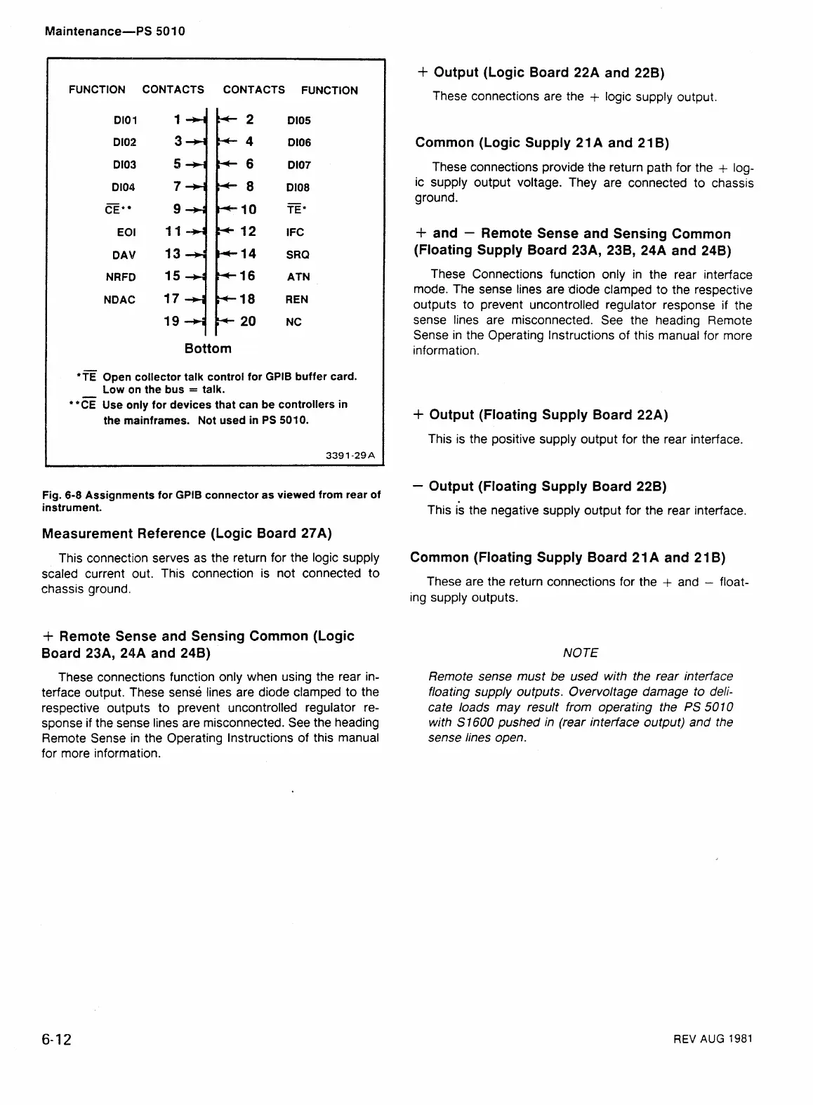
FUNCTION CONTACTS CONTACTS FUNCTION
Dl0 1
Dl02
Dl03
Dl04
CE*
EOI
D AV
NRFC)
NDAC
Dl05
Dl06
Dl07
Dl08
TE"
I
FC
SRQ
ATN
REN
NC
Bottom
"TE
Open collector talk control for GPlB buffer card.
Low en the bus
=
talk.
'*CE Use only for devices that can be controllers in
the mainframes. Not used in PS 5010.
Fig.
6-8 Assignments for GPlB connector as viewed from rear of
instrument.
Measurement Reference (Logic Board 27A)
This connection serves as the return for the logic supply
scaled current out. This connection is not connected to
chassis ground.
+
Remote Sense and Sensing Common (Logic
Board 23A, 24A and 24B)
These connections function only when using the rear in-
terface output. These sense lines are diode clamped to the
respective outputs to prevent uncontrolled regulator re-
sponse if the sense lines are misconnected. See the heading
Remote Sense in the Operating lnstructions of this manual
for more information.
+
Output (Logic Board 22A and 228)
These connections are the
+
logic supply output.
Common (Logic Supply 21
A
and 21 B)
These connections provide the return path for the
+
log-
ic supply output voltage. They are connected to chassis
ground.
+
and
-
Remote Sense and Sensing Common
(Floating Supply Board 23A, 238, 24A and 24B)
These Connections function only in the rear interface
mode. The sense lines are diode clamped to the respective
outputs to prevent uncontrolled regulator response if the
sense lines are misconnected. See the heading Remote
Sense in the Operating Instructions of this manual for more
information.
+
Output (Floating Supply Board 22A)
This is the positive supply output for the rear interface.
-
Output (Floating Supply Board 22B)
This
k
the negative supply output for the rear interface.
Common (Floating Supply Board 21 A and 21 B)
These are the return connections for the
+
and
-
float-
ing supply outputs.
NOTE
Remote sense must be used with the rear interface
floating supply outputs. Overvoltage damage to deli-
cate loads may result from operating the
PS
501 0
with
S1600
pushed in (rear interface output) and the
sense lines open.
REV
AUG
1981
 Loading...


