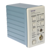
TCPA300 and TCPA400 Performance Verification
TCPA300/400 Amplifiers and TCP300/400 Series Current Probes Instruction Manual
5-11
c. Using the peak-peak measurement capability of the oscilloscope,
measure and record the peak-peak reading as M
2
in Table 5--7 or
Table5--8onpage5--11.
9. The system meets the bandwidth specification if the ratio of the s ignal
amplitude at the warranted bandwidth is at least 70% of the signal amplitude
at 3 MHz. Using the following calculation, verify system bandwidth:
correction factor
Ꮛ
M
2
M
1
Ꮠ
> 0.707
10. Verify that the calculated system bandwidth is within the limits specified for
all settings in the test record on page 5-- 16 for the TCPA300 (page 5--17 for
the TCPA400). Record the calculated system bandwidth in the test record.
Table 5- 7: TCPA300 bandwidth measurements
TEKPROBE interface cable Coaxial cable
Range
Vertical
gain
setting
Amplifier
output, p-p
Vertical
gain
setting
Amplifier
output, p-p
Bandwidth
filter and
generator
frequency
Correction
factor
1
M1 M2
1A/V 500 mA/div ~3 A 500 mV/div ~3 V 50 MHz 1.09
500 mA/div ~3 A 500 mV/div ~3 V 100 MHz 1.14
5A/V 1A/div ~7.5 A 200 mV/div ~1.5 V 50 MHz 1.16
10 A/V 1A/div ~7.5 A 100 mV/div ~0.75 V 50 MHz 1.11
50 A/V 2A/div ~15 A 50 mV/div ~300 mV 50 MHz 1.14
50 A/V
COMP
2
2A/div ~15 A 50 mV/div ~300 mV 50 MHz 1.00
1
The correction factor accounts for impedance differences between the 50 Ω voltage source and the TCPA amplifier at
higher frequencies.
2
Both 10 A/V and 50 A/V RANGE LEDs light.
Use Table 5--8 to record the measurements for the TCPA400 Amplifier.
Table 5- 8: TCPA400 bandwidth measurements
TEKPROBE interface cable Coaxial cable
Range
Vertical
gain
setting
Amplifier
output, p-p
Vertical
gain
setting
Amplifier
output, p-p
Bandwidth
filter and
generator
frequency
Correction
factor
M1 M2
1A/mV 100 A/ div ~500 A 100 mV/div ~500 mV 50 MHz 1.09

 Loading...