Troubleshooting and Error Codes
3-22
TCPA300/400 Amplifiers and TCP300/400 Series Current Probes Instruction Manual
Displaying Error Codes with the Probe Degauss Autobalance Button
This section describes the error codes that the amplifiers display using the
function indicator LEDs.
When an internal error condition exists, the amplifiers may generate error codes
when you press the PROBE DEGAUSS AUTOBALANCE button. The AC and
DC Coupling LEDs will flash alternately to indicate that error codes are being
displayed instead of normal conditions.
The four fault indicator LEDs above the ON/STANDBY s witch are used to form
a four-bit binary error code. The PROBE OPEN LED indicates the most
significant bit (MSB), and the NONCOMPATIBLE PROBE TYPE LED
indicates the least significant bit (LSB). See Figure 3-- 15.
To continue past an error code, press any button except ON/STANDBY.
However, the degauss will fail until the internal error condition is corrected and
the degauss operation is run again.
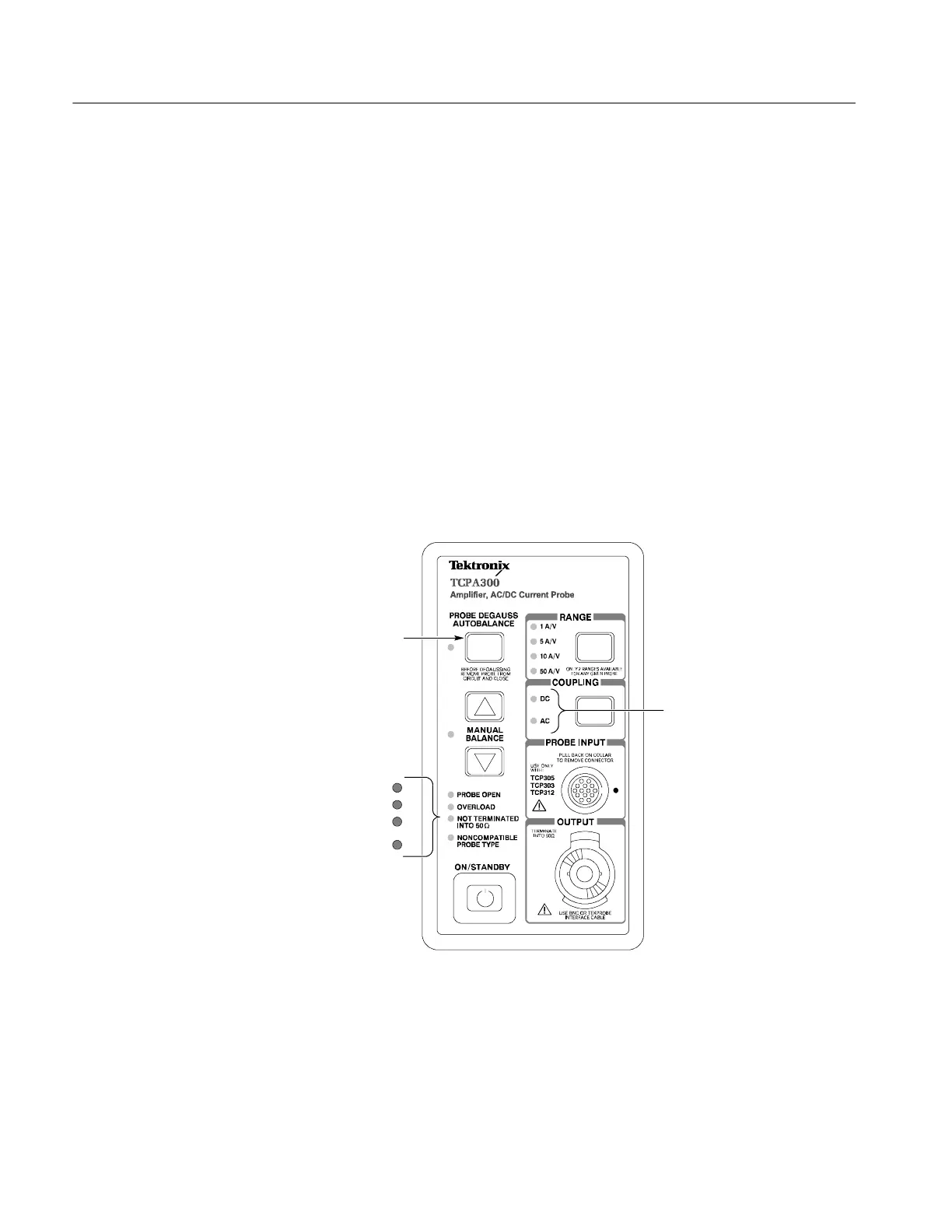
Press the PROBE
DEGAUSS AUTO
BALANCE button
Four--bit error code
is displayed here
MSB
LSB
AC and DC LEDs flash
alternately to indicate
error codes are being
displayed
Figure 3- 15: Error code display
For example, after you press the PROBE DEGAUSS AUTOBALANCE button,
if the AC and DC Coupling LEDs are flashing, and the NOT TERMINATED
INTO 50 Ω LED is illuminated, this indicates an Error Code 2 -- a null error in
the DC offset circuit occurred. S ee Figure 3--16 for an illustrated example.

 Loading...
