Reference Notes
TCPA300/400 Amplifiers and TCP300/400 Series Current Probes Instruction Manual
3-3
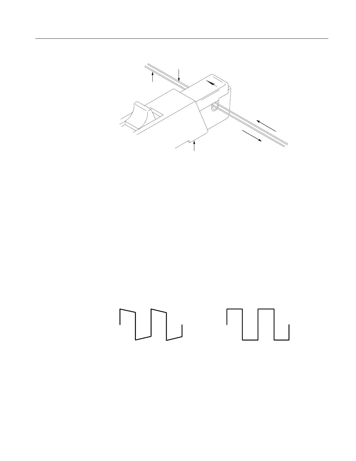
Conductor #2
Current probe
Conductor #1
Current
Current
Figure 3- 1: Measuring differential current and nulls
AC and DC Coupling
You can couple the signal input to the TCPA300 and TCPA400 with either DC or
AC coupling. DC coupling shows the DC and AC measurement components
while AC coupling removes the DC component from the displayed signal. When
you use AC coupling, make sure that the input DC current does not exceed the
probe specifications.
AC coupling will affect waveforms at frequencies higher than the AC Coupling
Low-Frequency Bandwidth. For example, pulsed currents may exhibit rolloff or
decreased amplitude. Figure 3--2(a) shows a low-frequency square wave using
AC coupling. The signal exhibits low-frequency rolloff. By changing the
amplifier coupling to DC, the pulse is displayed as truly square, as shown in
Figure 3--2(b).
(a) AC-Coupled signal
(b) DC-Coupled signal
Figure 3- 2: Effect of AC or DC coupling on low-frequency signals
If you are trying to examine a low-frequency signal that is superimposed on a
comparatively large DC component, you can resolve the signal by performing
these steps:

 Loading...
