TCP305 and TCP312 Performance Verification
5-24
TCPA300/400 Amplifiers and TCP300/400 Series Current Probes Instruction Manual
Rise Time
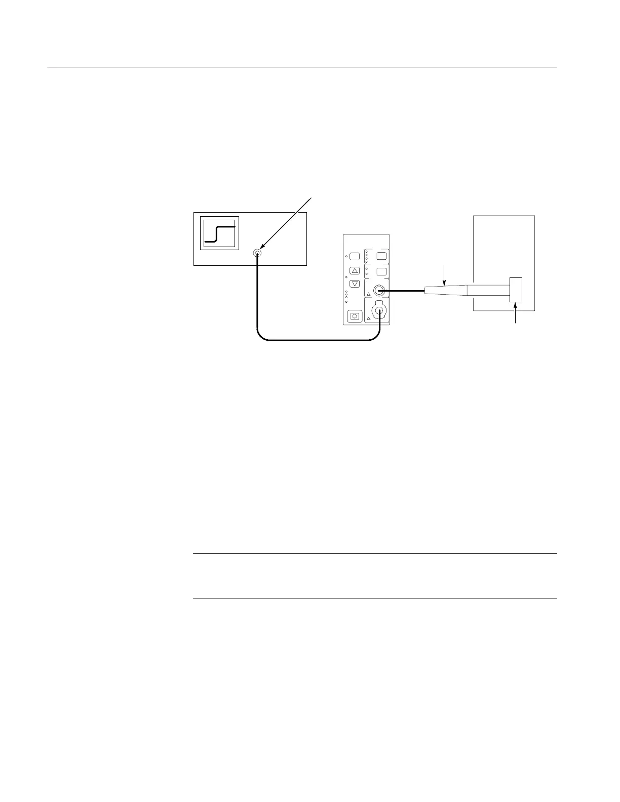
This procedure measures the rise time of the TC P305 and TCP312 Current
Probes. In this test you directly measure the rise time of a step input. Refer to
Figure 5--8 when making equipment connections.
Test oscilloscope
Current probe
HF current
loop
High amplitude
pulse generator
50 Ω oscilloscope input -- use the TekProbe
InterfaceCableorusea50Ω cable. (Add
50 Ω termination here if oscilloscope has
only high-impedance input.)
Figure 5- 8: Rise time test setup for the TCP305 and TCP312
1. If you are using a Tektronix oscilloscope that supports the TekProbe Level 2
Interface, use the TekProbe Interface Cable to connect the amplifier
OUTPUT to the oscilloscope input. If you are not using a Tektronix
oscilloscope that supports the TekProbe Level 2 Interface, use a 50 Ω BNC
cable. If the input impedance of your oscilloscope is 1 MΩ, connect a 50 Ω
feedthrough termination at the oscilloscope input. Do not connect the
termination at the amplifier output.
2. Connect the current probe to the amplifier PROBE INPUT.
3. Connect the HF current loop to the high amplitude pulse generator output.
NOTE. If your oscilloscope cannot trigger on the pulse, use another BNC cable
to connect the trigger output of the pulse generator to the trigger input of the
oscilloscope. Configure the oscilloscope for an external trigger.
Make or verify the equipment settings in Table 5--14 on page 5--25:
Equipment C onnections
Equipment Sett ings
 Loading...

