TCP305 and TCP312 Performance Verification
5-28
TCPA300/400 Amplifiers and TCP300/400 Series Current Probes Instruction Manual
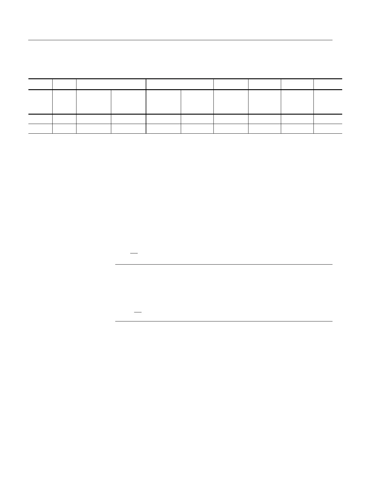
Table 5- 16: Bandwidth test for the TCP305 and TCP312
Oscilloscope vertical gain TCPA300 output
Probe Range
w/TEK-
PROBE
cable
w/BNC
cable
w/TEK-
PROBE
cable
w/BNC
cable
M1 @3 MHz
ref freq
BW freq
M2 @
warranted
BW freq
Calcula-
tion
1
TCP305 5A/V 10 mA/div 2mV/div ~60 mA p--p ~12 mV p--p 50 MHz
TCP312 1A/V 10 mA/div 10 mV/div ~60 mA p--p ~60 mV p--p 100 MHz
1
Use the formulas in step 9 on page 5-28.
7. Set the oscilloscope time base to 4 or 5 ns/division. Increase the signal
generator frequency to the warranted bandwidth. Refer to Table 4-- 1 on
page 4--1.
8. Using the peak-peak measurement capability of the oscilloscope, measure
and record the peak-peak reading as M
2
.
9. The probe meets the bandwidth specification if the ratio of the signal
amplitude at the warranted bandwidth is at least 70.7% of the signal
amplitude at 3 MHz. Using the following calculation, verify probe band-
width for the TCP305:
Ꮛ
M
2
M
1
Ꮠ
> 0.707
NOTE. The impedance of the HF current loop used in this test changes between
3 MHz and 100 MHz. Typically the impedance changes from 50 Ω at 3 MHz to
59 Ω at 100 MHz. Thus you can substitute the following equation to make this
test more accurate for the TC P312:
(
1.18
)
Ꮛ
M
2
M
1
Ꮠ
> 0.707
This completes the performance verification for the TCP305 and TCP 312
probes.
If the TCP305 and TCP312 probes fail any of the verification tests, refer to the
Adjustments section for servicing information.

 Loading...
