TCPA300/400 Amplifiers and TCP300/400 Series Current Probes Instruction Manual
2-1
Control Summary
This section describes the function of each TCPA300 and TCPA400 front panel
control and connector. The overview in Figure 2--1 is followed by a detailed
description.
Some seldom-used functions do not appear in Figure 2-- 1. These functions are
completely discussed in the detailed descriptions that follow Figure 2 --1.
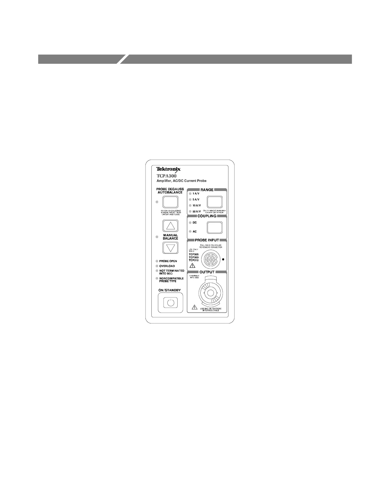
The PROBE DEGAUSS AUTOBALANCE button
removes residual magnetism from the attached
current probe. A multi-color LED indicates the
status of the degauss circuit.
The four probe error lights indicate the following
faults: PROBE OPEN, OVERLOAD (current or
temperature), NOT TERMINATED INTO 50 Ω
and NONCOMPATIBLE PROBE TYPE.
The current probes connect to the TCPA300 and
TCPA400 at the PROBE INPUT connector.
The RANGE button toggles between the two
scale factors that are available for the attached
probe (TCPA300 only). LEDs indicate the
selected range.
The MANUAL BALANCE buttons allow you to
fine-adjust DC offset from the amplifier. The
adjacent LED lights when one of the buttons
has been pressed.
The ON/STANDBY button turns on power to
the amplifier.
The TCPA300 and TCPA400 output appears at
the OUTPUT connector. Connect this to a 50 Ω
input of your oscilloscope.
The COUPLING button selects AC or DC probe
coupling, as indicated by the LEDs.
Figure 2- 1: The TCPA300 front panel

 Loading...
