TCP303 and TCP404XL Performance Verification
5-40
TCPA300/400 Amplifiers and TCP300/400 Series Current Probes Instruction Manual
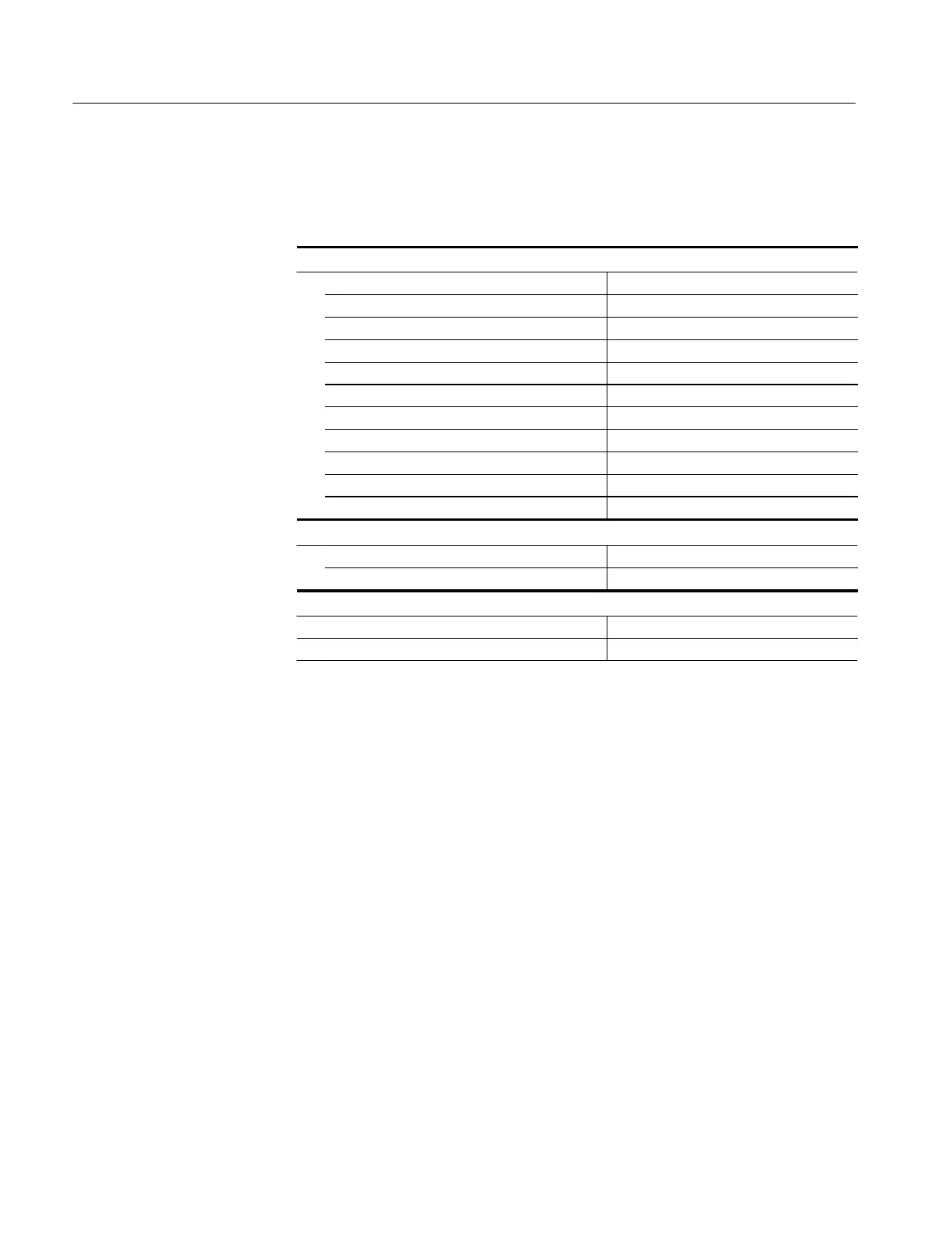
Make or verify the equipment settings in Table 5--21.
Table 5- 21: Equipment settings for bandwidth
Oscilloscope
Vertical input impedance 50 Ω
Time base 200 ns/division
Record length 500
Coupling DC
Offset 0 V (mid-scale)
Trigger type Edge
Trigger mode Auto
Trigger position 50%
Acquisition mode Average
Number of waveforms to average 8
Measurement type Peak-to-Peak
Leveled sine wave generator
Frequency 3MHz
Amplitude 3V
p-p
TCPA300
Coupling DC
Range 5A/V
1. Do not clamp the current probe around any conductor, but make sure the
jaws are locked shut.
2. Press the amplifier PROBE DEGAUSS AUTOBALANCE button. Wait for
the degauss/autobalance routine to complete before proceeding. The routine
is complete when the indicator light turns green.
3. Clamp the current probe around the H F current loop.
4. Enable the output of the leveled sinewave generator.
5. Verify the output level is what is listed for the probe in Table 5--22.
6. Using the peak-peak measurement capability of the oscilloscope, measure
and record the peak-peak reading as M
1
in Table 5--22 on page 5--41 .
7. Set the oscilloscope time base to 40 or 50 ns/division. Increase the signal
generator frequency to the warranted bandwidth. Refer to the test record for
the warranted bandwidth.
8. Using the peak-peak measurement capability of the oscilloscope, measure
and record the peak-peak reading as M
2
.
Equipment Sett ings
Procedure
 Loading...

