Table of Contents
TCPA300/400 Amplifiers and TCP300/400 Series Current Probes Instruction Manual
v
List of Figures
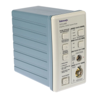
Figure 1--1: Typical TCPA300/400 current measurement system 1--1...
Figure 1 -- 2: Using the probe holders 1--6..........................
Figure 1--3: Equipment locations in the travel case 1--7..............
Figure 1 -- 4: Connecting and disconnecting a current probe
to the amplifier 1--9........................................
Figure 1--5: TCP312 and TCP305 slide operation 1--10...............
Figure 1--6: TCP303 and TCP404XL slide operation 1--11............
Figure 1--7: Current probe polarity 1--13...........................
Figure 2--1: The TCPA300 front panel 2--1........................
Figure 3 -- 1: Measuring differential current and nulls 3--3............
Figure 3 -- 2: Effect of AC or DC coupling on low-frequency signals 3--3.
Figure 3 -- 3: Applying the amp-second product rule 3--5..............
Figure 3--4: Duty cycle calculation 3--6............................
Figure 3--5: Increasing the DC measurement range 3--9..............
Figure 3--6: Increasing probe sensitivity 3--10.......................
Figure 3--7: Setup for measuring charging current 3--12..............
Figure 3--8: Charge Current Waveforms 3--12.......................
Figure 3 -- 9: Measuring inductance with a low-impedance source 3--13..
Figure 3--10: Linear curr ent vs. time ramp 3--14.....................
Figure 3 -- 11: Measuring inductance with a high-impedance source 3--15.
Figure 3 -- 12: High-impedance source current ramp 3--15.............
Figure 3 -- 13: Measuring the number of turns in a coil 3--16...........
Figure 3--14: Turns measur ement using reference coil 3--17............
Figure 3--15: Error code display 3--22..............................
Figure 3--16: Interpreting the error code display 3--23................
Figure 4 -- 1: Probe jaw dimensions (nominal) 4--4...................
Figure 4 -- 2: Frequency derating-- TCP312 4--8......................
Figure 4 -- 3: Frequency derating-- TCP305 4--8......................
Figure 4 -- 4: Frequency derating-- TCP303 4--9......................
Figure 4--5: Frequency derating--TCP404XL 4--9...................
Figure 4--6: Insertion impedance graphs for the curr ent probes 4--10...
Figure 4--7: Specified operating area of the probes 4--11..............

 Loading...