© Telect, Inc., All Rights Reserved, 124317-10 A0
1.509.926.6000 :: telect.com
8
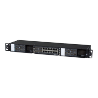
ELF System
Copper / Fiber :: ELF Family
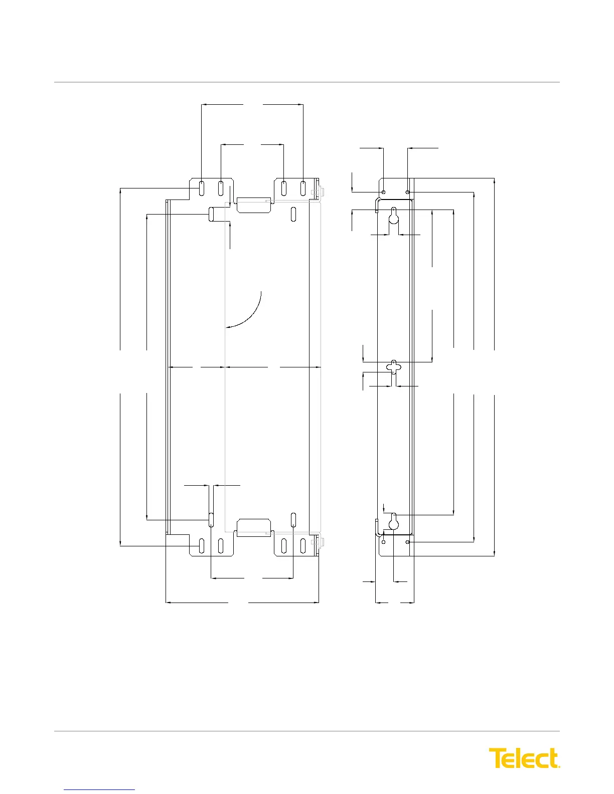
18.71 (475.2)
16.00 (406.4)
0.75 (19.0)
0.25 (6.35)
5.30
(134.6)
3.30
(83.8)
4.30
(109.2)
8.00
(203.2)
0.50 (12.7)
0.25 (6.35)
8.00 (203.2)
16.00 (406.4)
18.31 (465.1)
19.77 (502.2)
0.875 (22.2)
0.95 (24.1)
2.03 (51.5)
0.50 (12.7)
0.91 (23.0)
1.25
(31.8)
Outline of ELF Chassis
3.00 (76.2)
5.00 (127.0)
Figure 5 - Wall-Mount ELF Chassis Bracket Dimensions
Typical wall installations are shown in the following illustrations. Telect recommends that the tie bar on the rear
of the ELF Chassis be removed when installing in the Wall-Mount ELF Chassis Bracket. Also, when installing
rear access ELF modules, Telect recommends including a minimum 2-ft (600-mm) service loop for any cabling or
wiring intended for the rear of the ELF module(s). Don’t forget to install a ground wire on the ELF Chassis, as
shown on Page 7.