iTRANS 2
FIXED POINT SINGLE OR DUAL GAS MONITOR
WITH DUAL ANALOG OUTPUTS
USER MANUAL
Revision 7.0
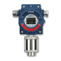
5.5.4 Calibration
Calibration is the next available option. Calibration is
designated with a “C” in the status bit. A 10 second timer is
displayed on the bottom line of the LED display. To initiate
calibration, place the magnetic wand over CH2 during the
10-
second countdown. If you do not initiate calibration
during the 10-second countdown, the will return to
the Normal Operating Mode. If you initiate calibration, the
status bit will start to flash and the will enter the
zeroing process.
Figure 5-8 Sample Calibration
Display
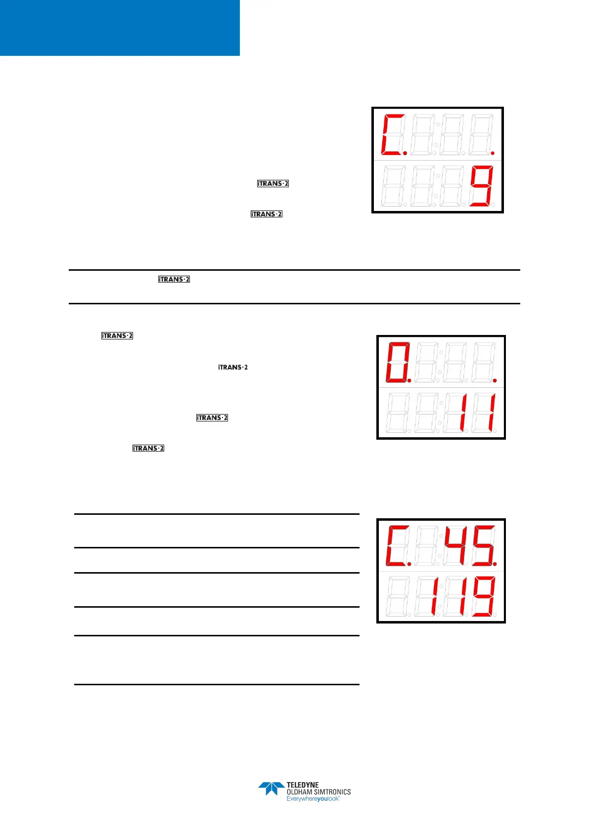
NOTE: Before the will calibrate, the unit will enter the zeroing process. Please make sure
that you apply Zero Air to the instrument while it is zeroing.
The will automatically zero before calibration.
Zeroing is designated with a flashing “0” in the status bit.
Once zeroing is complete, the will automatically enter
the calibration routine. Calibration is designated with a
flashing “C” in the status bit.
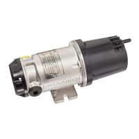
After zeroing finishes, the is ready to calibrate. When
the flashing “C” appears on the display, apply calibration
gas. As the responds to the gas, the current reading
will be displayed on the top line of the LED display. To abort
calibration at any time, place the magnetic wand over CH1.
Check and verify span setting before starting a
calibration.
See Appendix D for a complete list of factory default
span gases.
Flow rate for calibration is 0.5 liter per minute (LPM)
except for NH
3
, ClO
2
, Cl
2
, NO
2
, SO
2
, and HCl which require
1.0 LPM.
Figure 5-9 Sample Zeroing
Display
Figure 5-10 Apply CalGas Display