iTRANS 2
FIXED POINT SINGLE OR DUAL GAS MONITOR
WITH DUAL ANALOG OUTPUTS
USER MANUAL
Revision 7.0
Figure A - 6 Power and Signal Connector J1 on HART Supported
9.2.1 HART 4-20mA Wiring (CH-1)
CH-1 and GND on J1 connector are used as HART 4-20mA interface terminals. The HART 4-
20mA output must be loaded with at least 250 ohms of impendence to properly establish the
HART communication. Some devices receiving the 4-20mA output already have a large enough
terminating resistor installed from the factory, but others may need additional resistance to be
added. This is accomplished by adding a resistor in series with the output from HART board,
preferably at the controller end of the 4-20mA current loop. Adding the additional resistor at the
controller allows the HART handheld device to be connected anywhere in the loop, because it
must have the full 250 ohm load after its connection point to function properly. If the additional
resistor is added at the transmitter, in CH-1, the HART handheld device will only be able to access
variables locally, at the transmitter.
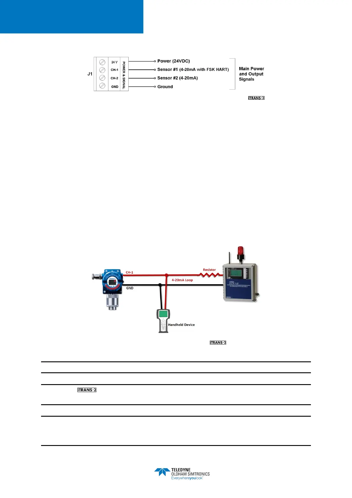
The Figure A - 7 shows a 150 ohm resistor added to the output loop since the controller has a
100 ohm terminating resistor installed from the factory.
Figure A - 7 Example of HART Supported Wiring
NOTE: Use supplied green conductor for enclosure ground.
NOTE: The is a 3- or 4-wire 4-20mA device. For dual sensor configuration you must
have a second 4-20mA signal wire pulled to the unit.
NOTE: When not using isolated 4-20mA or HART 4-20mA outputs, use the supplied resistors to
connect CH-1 and CH-2 to GND. If these resistors are not connected and the 4-20mA outputs
are not used, a “P” will appear on the display, indicating an open loop condition.