TTE Combo Communication Module – Installation and Programming Manual
8
2. HARDWARE INSTALLATION
TTE Combo is a universal communication module which provides the opportunity for connection to
different types of control panels and reporting for events to a monitoring station and/or end User.
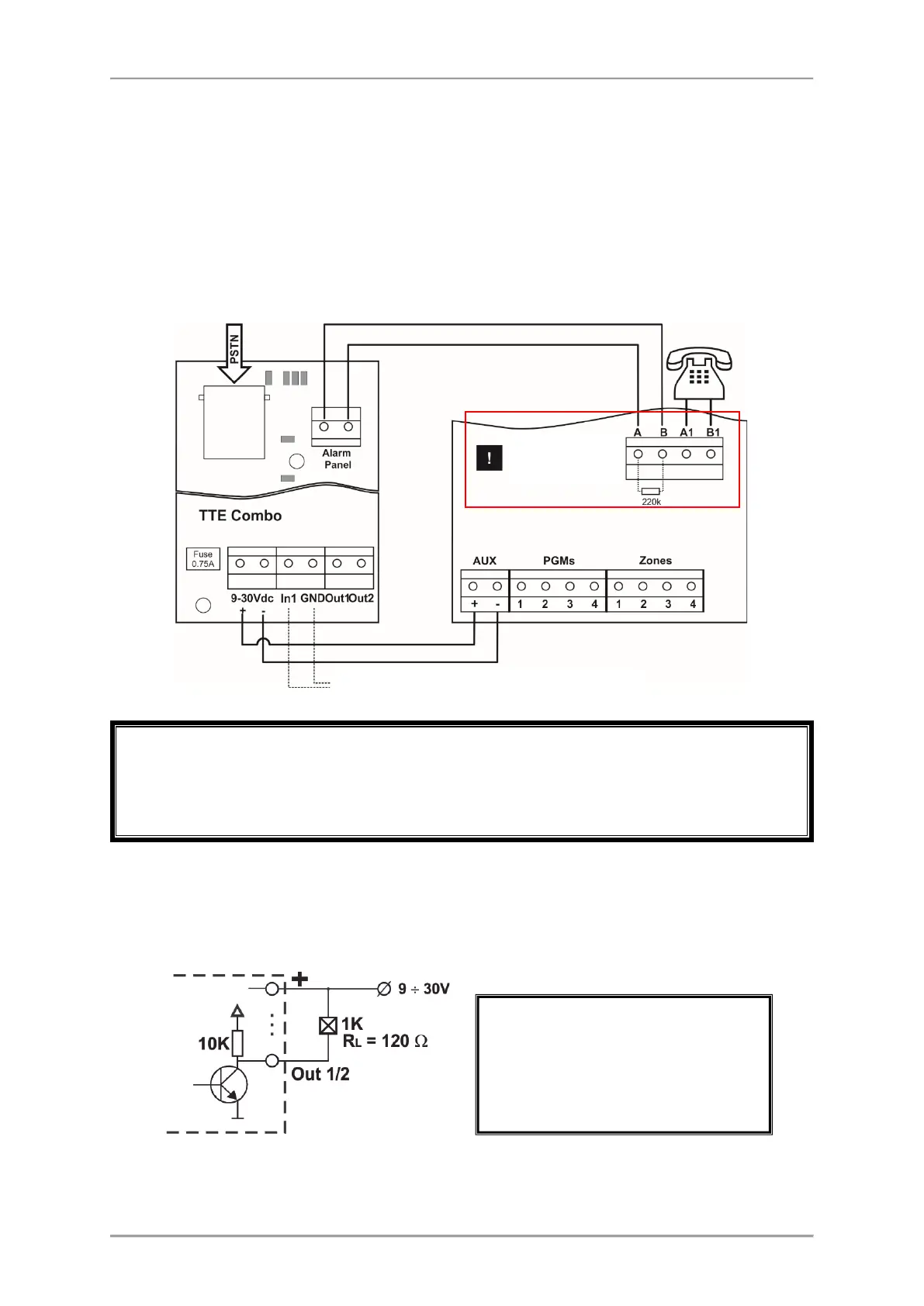
2.1 Connection to Burglary Alarm Control Panel
TTE Combo is mounted into the panel’s installation box. The module can be powered on directly
from the +/- AUX outputs (required 9-30VDC) of the control panel as observing the polarity; or from
an external power supply unit.
If the terminals A1 and B1 (on the presented diagram) are not used for connection of a telephone
device, the terminals must be terminated with a 220k resistance! If the A1 and B1 terminals are
missing the resistance of 220k must be connected to A and B terminals!
2.2 Internal Structure of the Outputs
TTE Combo has 2 outputs OC type that can be used for small home automation projects.
The Internal structure of the output is presented on the following schematic diagram:
All electrical connections must be
done ONLY when the mains and back-
up power supplies of the module are
switched off!
Burglary Alarm Control Panel
Connection of a Tamper switch (optional)