TTE Combo Communication Module – Installation and Programming Manual
9
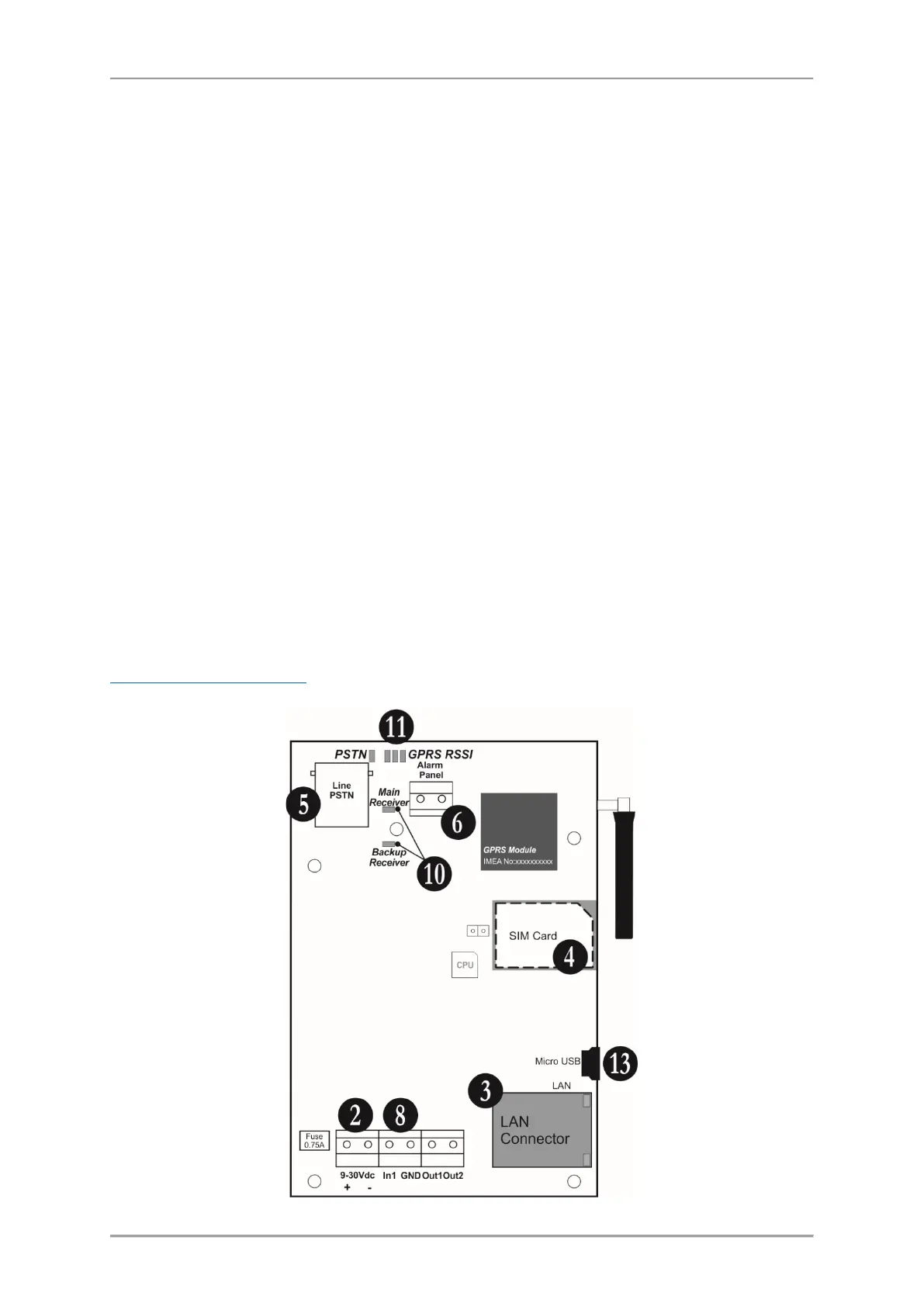
2.3 Basic Installation Steps
(for full configuration)
1. Turn off the main and backup power supply of the control panel.
2. Connect the power supply of the module (9-30VDC) – from the control panel or external power
unit.
3. Run the CAT-5 Ethernet cable for LAN connection through any suitable cable opening of the box
and connect it to the LAN connector of the module.
4. Switch off the PIN protection code of the SIM card and place it into the SIM interface holder of TTE
Combo module.
5. Run the PSTN cable through any suitable cable opening of the box and connect it to the LINE
connector of the module.
6. Connect the digital communicator of the control panel (A and B terminals) to ALARM PANEL
terminals of TTE Combo.
7. Connect the phone device to A1 and B1 terminals of the control panel; in case the phone device is
not used – terminate the A1 and B1 terminals with 220k resistor.
8. Connect t a TAMPER switch (or TAMPER zone) to IN1 terminals of TTE Combo.
9. Turn on the main and backup power supply of the panel.
10. Wait for the connection with the Main and/or Backup Receiver station - up to 90 sec the
Main/Backup Receiver LEDs are blinking in red. The established connection is indicated with blinking
in green.
11. Check the signal strength - 2 or 3 RSSI LEDs are lighting on in green. If the signal strength is poor,
change the location of the module or use external antenna.
12. The module is in normal operation mode - the PSTN LED lights on in green, and Main/Backup
Receiver LEDs are blinking in green (depends on the application).
13. Set the parameters of ТТЕ Combo module using ProsTE programming software – see also
3. Programming with ProsTE
.