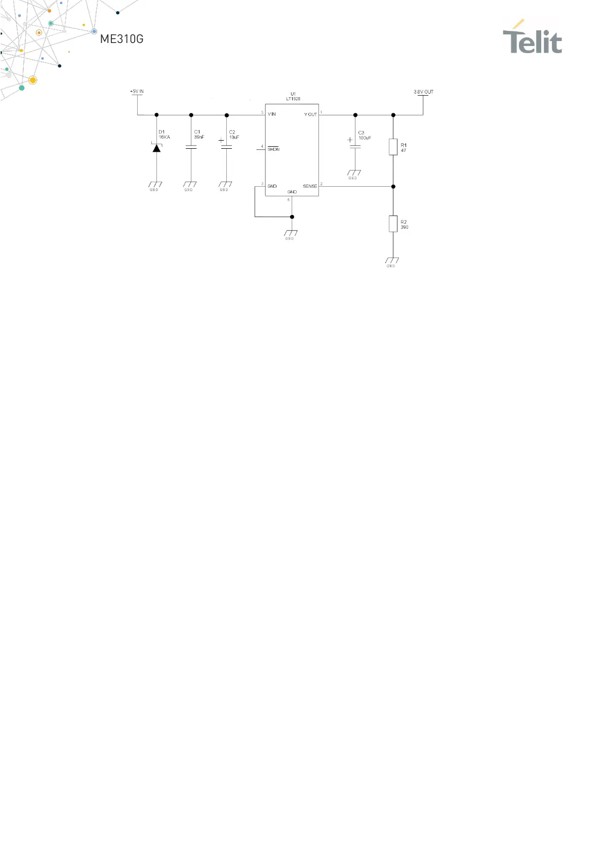
An example of a linear regulator with 5V input is:
Figure 3: Example of a linear regulator with 5V input
4.3.1.2 +12V Source Power Supply Design Guidelines
The desired output for the power supply is 3.8V, so due to the large difference between
the input source and the desired output, a linear regulator is not suitable and shall not
be used. A switching power supply will be preferable because of its better efficiency.
• A regulator must be provided to absorb current peaks. The recommended
switching regulator is 500kHz. Due to its smaller inductor size and faster
transient response, it has a higher switching frequency.
• The frequency and selection of switching design are related to the application.
Since the switching frequency could also generate EMC interference.
• For a PB car battery, the input voltage may rise up to 15.8V and this must be
considered when selecting components. All components in the power supply
must support this voltage.
• A low ESR bypass capacitor must be included to stop the current absorption
peaks near the module . The recommended capacitor is 100μF.
• Make sure that the low ESR capacitor on the output of the power supply is rated
at least 10V.
• For Car applications, a spike protection diode must be placed close to the
power input, to clean the power supply spikes.

 Loading...


