• Keep the antenna line away from GSM RF lines and power supply lines.
• If there are noisy EM devices around the PCB hosting the module, such as fast
switching ICs, take care of the antenna line shielding by burying it inside the PCB
layers and surrounding it with Ground planes, or shielding it with a metal frame
cover.
• For an EM noise environment, make sure to shield the antenna line with a metal
frame cover or PCB layers and wind it with the Ground plane.
• For an EM noise free environment, shield the antenna line with a strip-line on the
superficial copper layer. The line attenuation will be lower than the buried one.
8.2.2 Hardware-based Solution for GNSS and LTE Coexistence
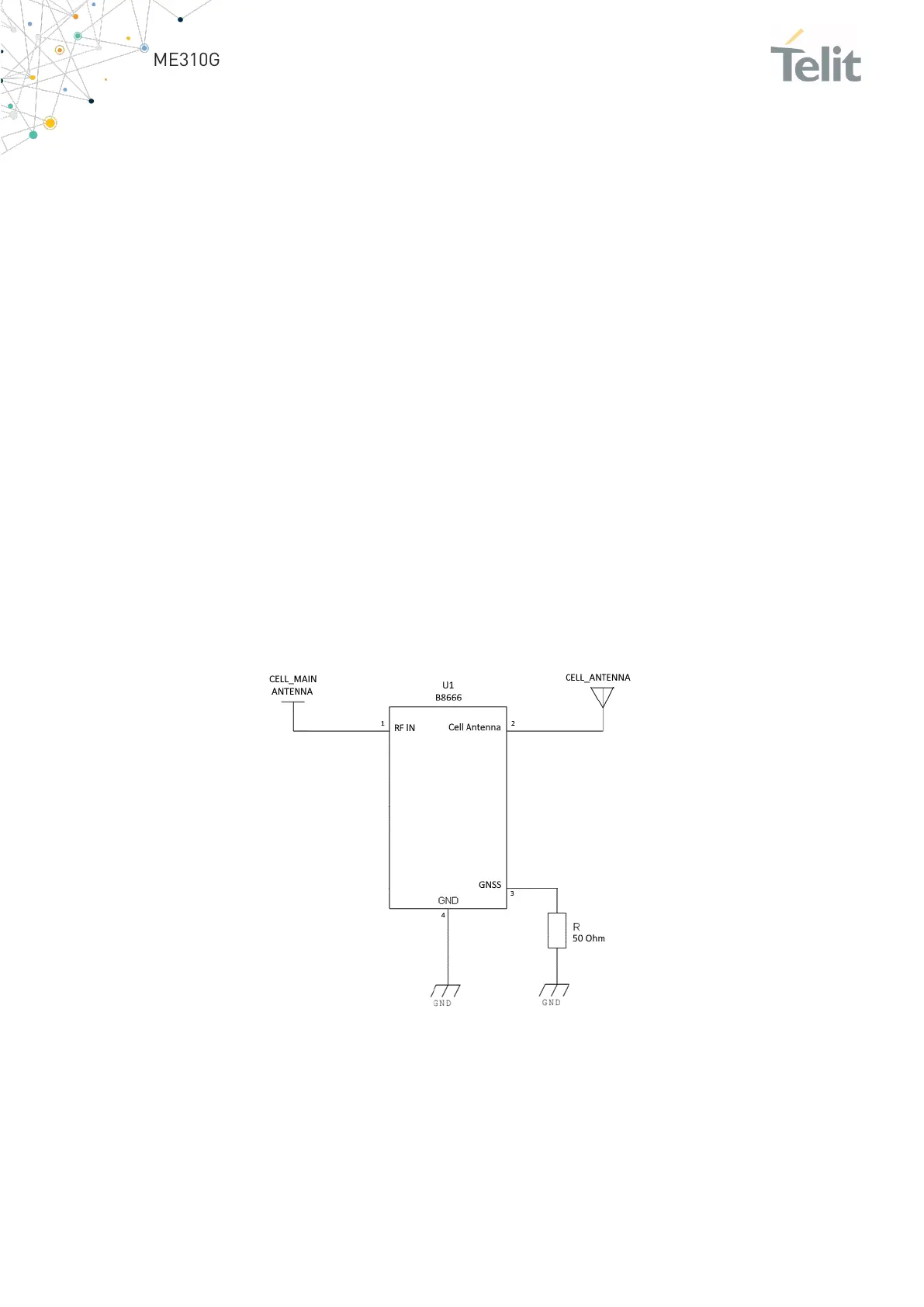
If the decoupling between the LTE and GNSS antennas is low in a stand-alone GNSS
receiver, the LTE transmission may desensitize the GNSS receiver. To protect the GNSS
receiver from LTE out-of-band emissions, include a SAW filter on the LTE side as
described in the diagram below.
There is no condition to degrade the GNSS receiver embedded in the ME310G1 module
while it is in use. So filtering on the LTE is not mandatory as the LTE and GNSS cannot be
active at the same time.
Figure 16: SAW filter on LTE side
8.3 GNSS Antenna Requirements
GNSS active antenna must be integrated into the application.

 Loading...


