ME310G1 Hardware Design Guide
1VV0301588 Rev. 16 Page 45 of 95 2021-10-27
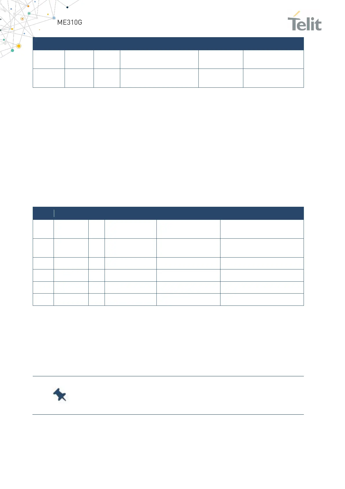
Auxiliary UART
(TX Data to DTE)
Auxiliary UART
(RX Data from DTE)
Table 31: ME310G1 serial port signals
5.8 General Purpose I/O
The Telit ME310G1 module includes a set of configurable digital input and output pins
(CMOS 1.8V). The Input pads can only be read. They report the digital value (high or low)
present on the pad at the time of reading. The Output pads can only be written or queried
and set the value of the pad output.
An alternate function pad is controlled internally by the module firmware and depends
on the function implemented.
The following are the available GPIO:
Alternate function DTR
INPUT - PU (100K)
Table 32: ME310G1 available GPIO
5.8.1 Using a GPIO as INPUT
GPIO pads, when used as inputs, can be connected to the digital output of another device
to report its status. Make sure the external device is compatible at interface levels with
the 1.8V CMOS levels of the GPIO.
Note: To avoid back power, it is recommended to avoid applying any
HIGH logic level signal to the digital pins of the ME310G1 when the
module is powered off or during an ON/OFF transition.

 Loading...


