ME310G1 Hardware Design Guide
1VV0301588 Rev. 16 Page 46 of 95 2021-10-27
5.8.2 Using a GPIO as OUTPUT
GPIO pads, when used as outputs, may drive the 1.8V CMOS digital devices or compatible
hardware. When set as outputs, the pads have a push-pull output and therefore the pull-
up resistor may be omitted.
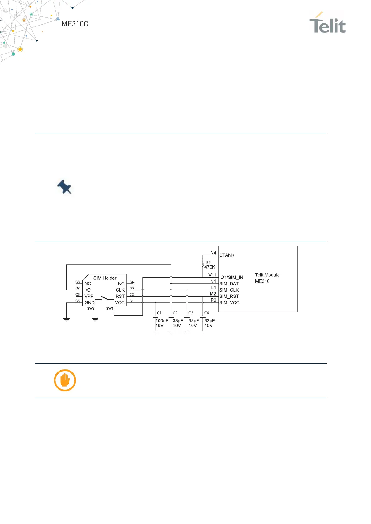
5.9 External SIM Holder
Refer to the SIM Holder Design Guide, 80000NT10001A.
Note: There is no dedicated signal (SIMIN) for “Presence SIM” in the
Telit ME310G1 module pinout.
This feature may be performed by connecting the GPIO_01 (Pad V11)
or GPIO_02 (Pad V13) or GPIO_03 (Pad D7) or GPIO_04 (Pad D9) to the
switch embedded into the sim-holder.
SIM detection may be configured by a specific AT Command.
Refer to the SW User Guide or AT Commands Reference Guide for a
complete description of this function.
Figure 10: SIM Holder schematic
Warning: Pull-up 470K is required across CTANK (ball N4) and switch
embedded in the sim-holder
5.10 ADC Converter
The Telit ME310G1 module includes an AD converter. It can read a voltage level in the
range of 0÷1.8V applied on the ADC pin input, store it and convert it to 10-bit words.
The input lines are called ADC (available on Pad B18).

 Loading...


