EasyManua.ls Logo

Telit Wireless Solutions ME310G1 - Recommendations for ME310 G1-WW, ME310 G1-WWV, ME310 G1-W2, and ME310 G1-W3

Telit Wireless Solutions ME310G1
95 pages
To Next Page IconTo Next Page
To Previous Page IconTo Previous Page
Loading...
ME310G1 Hardware Design Guide
1VV0301588 Rev. 16 Page 68 of 95 2021-10-27
Not Subject to NDA
10.1.4 Recommendations for ME310G1-WW, ME310G1-WWV, ME310G1-
W2, and ME310G1-W3
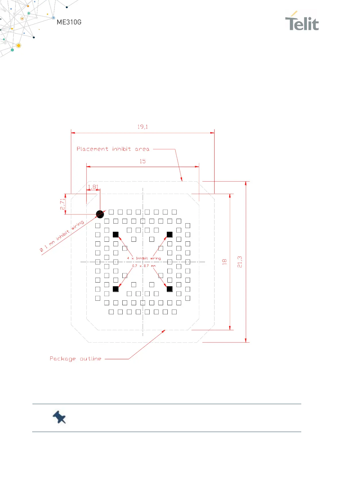
This section illustrates the application placement inhibit area for the ME310G1 models
WW, WWV, W2, and W3. To facilitate reworking, the recommended placement is shown
in the figure below.
It is recommended to avoid contact of mechanical parts with a SMT component of the
module.
Figure 25: ME310G1-WW, ME310G1-WWV, ME310G1-W2, and ME310G1-W3 Recommendations
Note: The region under INHIBIT WIRING must be clear from signal or
ground paths.

Table of Contents

Other manuals for Telit Wireless Solutions ME310G1

Related product manuals