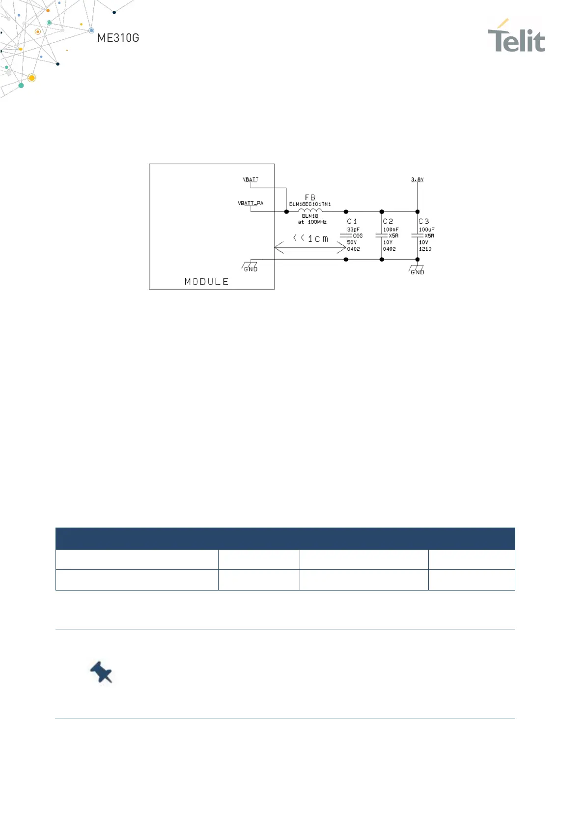
• The insertion of the EMI filter on the VBATT pins is recommended in those
designs where the antenna is placed near batteries or power supply lines. For
this purpose, a Murata BLM18EG101TN1 or Taiyo Yuden P/N FBMH1608HM101
ferrite bead can be used.
The below figure shows the recommended circuit:
Figure 5: Recommended circuit
4.4 RTC Supply
RTC is functional when ME310G1 is in PSM or OFF state and VBATT pin is supplied.
RTC settings are lost when the VBATT supply is disconnected.
4.5 PWRMON Power-on Monitor
PWRMON is always active (output high) when the module is powered ON (module
powered ON indication) and cannot be set to a LOW level with AT commands.
This signal is present on pin R1.
The following are the operating range characteristics of the PWRMON signal:
Note: The Output Current MUST never be exceeded. To avoid
excessive current consumption, be sure to carefully design the
application section.
If the current exceeds the limit, the module may shutdown.

 Loading...


