MA365 • Rev. A2 33
Tellabs
®
6325 Edge Node 2 Installation Information
Ground to 48 VDC The Tellabs 6325 node cabinet must always be tied to a suitable earth reference
potential as described below. The DC power interface of the Tellabs 6325 node
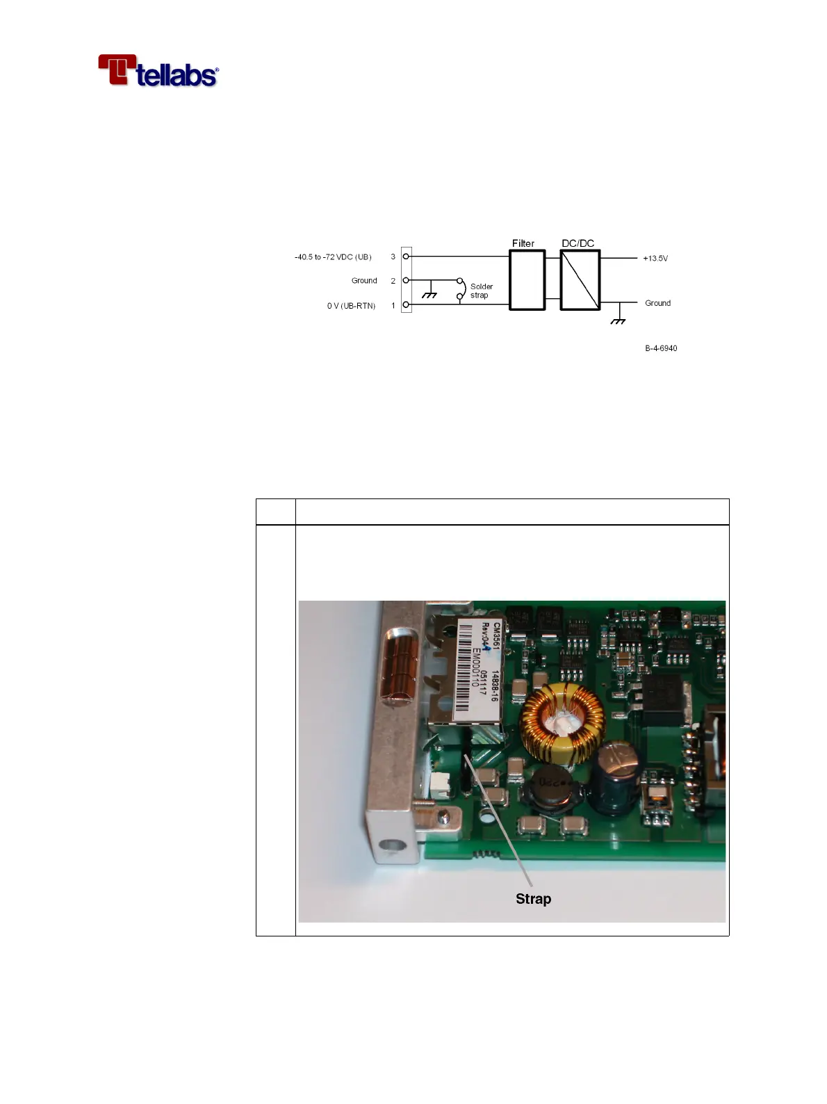
is galvanically insulated from the cabinet. The positive pole of the DC supply
(0 VDC) is default connected, by a solder strap on the PS-DC module, to the
ground connector of the power supply plug as shown in the figure. This is
called DC-C in ETSI/ITU terminology.
To change the 48 VDC
grounding
If the DC-I grounding strategy is preferred (UB-RTN is floating relative to
GND/Chassis) the solder strap on the PS-DC module must be removed as de-
scribed in this procedure.
The positive pole of the DC power supply (0 VDC) must always be connected
to the same earth potential at the station DC power supply (Power Distribu-
tion Panel).
Step Action
1
If you want to change the default DC-C grounding (0 V DC connect-
ed to ground) to the DC-I grounding (0 V DC separated from
ground) then cut the strap in the PS-DC module as shown on the fig-
ure below.