34 MA365 • Rev. A2
Tellabs
®
6325 Edge Node 2 Installation Information
External ground to the
Tellabs 6325 node
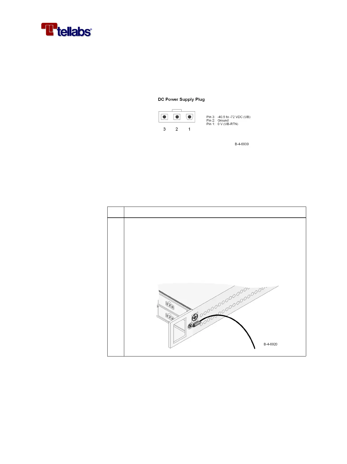
It is vital that the Tellabs 6325 node is properly earthed/grounded. When in-
stalled in a rack, the Tellabs 6325 node cabinet will be tied to the rack reference
potential through the mounting brackets (earth, ground potential) and the
ground pin (pin 2) of the power supply plug as shown in the figure.
Note: Make sure that the subrack brackets are installed on unpainted rack ar-
ea.
To connect external
ground to the Tellabs
6325 node
When not installed in a rack, the cabinet must be tied to an earth reference po-
tential through the ground pin (pin 2) of the power supply plug or by connect-
ing an extra ground wire to one of the cabinet screws. Please follow this pro-
cedure.
Step Action
1
Connect an external ground wire to the subrack as shown in the fig-
ure.
Use a yellow/green flexible ground cable, minimum AWG#18
(0.75 mm
2
), fit the cable with a tin plated ring tongue terminal (in or-
der to avoid corrosion and obtain a low impedance connection) and
use the M4x8 screw and washer (supplied with the subrack) to attach
the wire.