MA365 • Rev. A2 35
Tellabs
®
6325 Edge Node 2 Installation Information
To connect the DC
power
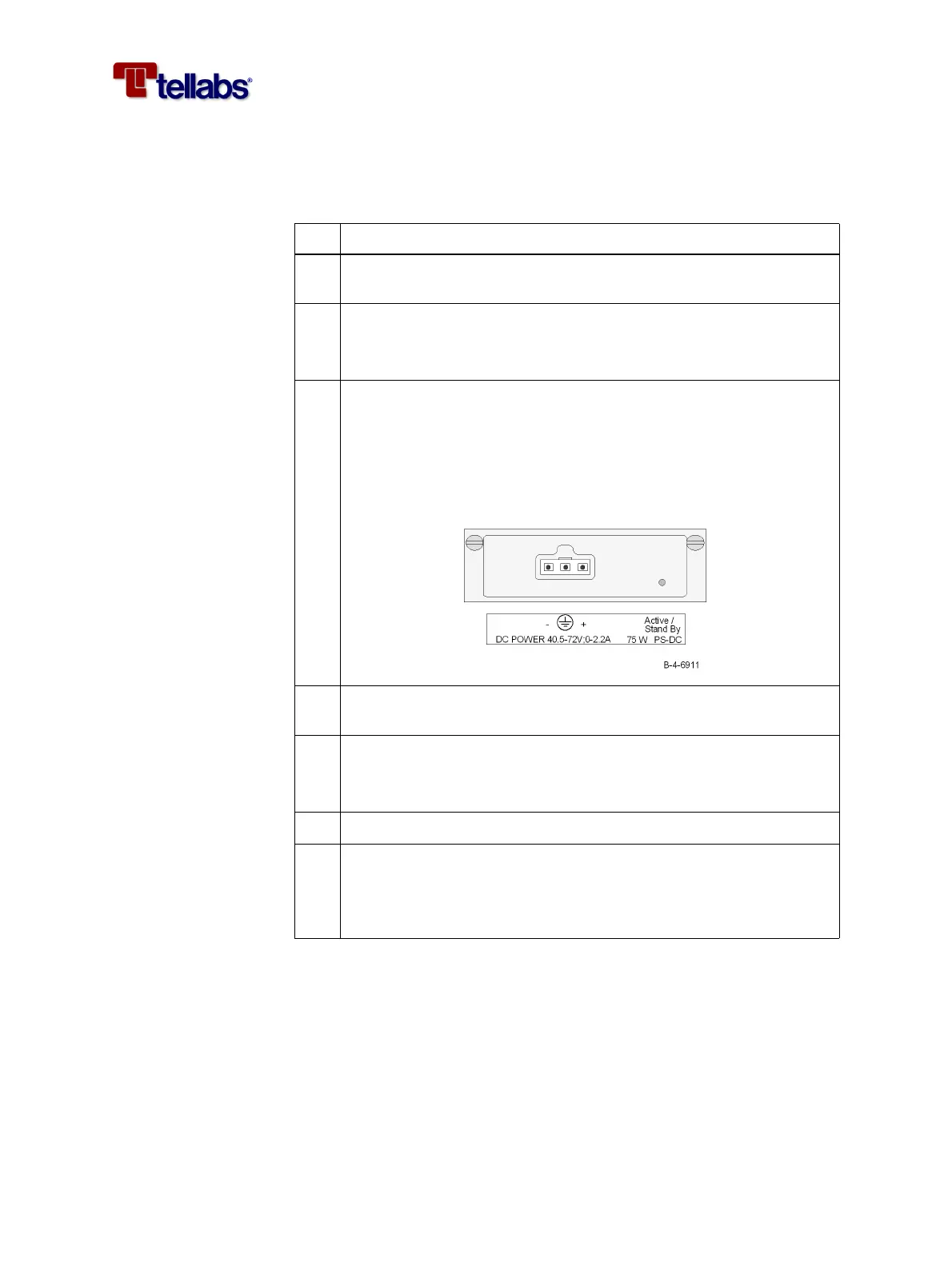
The following procedure describes how to connect the DC power cable to the
PS-DC module. Go to ‘To connect the external AC/DC power adapter’ on
page 36 if only AC power is used.
Step Action
1
Make sure that the -48/60 VDC (tolerance -40.5 to -72 VDC) power is
present at the power distribution panel (PDP)
2 Disconnect power by either switching off or removing the fuses from
the PDP.
Note: There is no built-in power switch on the Tellabs 6325 node.
3 Connect the power supply cable (with ground) to the DC input plug
(3 pole Molex mini-fit).
You may use the cable WK-500Z-02.6-01. The coding of the open
ended cable is shown in ‘Color coding of open ended cables’ on page
66. If you decide to use your own cables, you must use a 3-wire cable
with minimum AWG#18 (0.75 mm
2
).
4 Connect the ground wire of the power cable to the ground/earthing
of the PDP.
5 Connect the -48/60 VDC power wire to the PDP.
Note: Be sure that the poles are correct when you connect the power
cable.
6 Connect the UB-RTN (0V) wire to the PDP.
7 Connect power by either switching on or reinserting the fuses from
the PDP.
The power supply has been connected correctly when the green LED
on the PS-DC module is lit (either constantly or flashing).