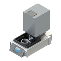
Single Station Vicat Test Apparatus
1.0360
3
List of Figures Page:
Figure 1: Connections .................................................................................................................................... 8
Figure 2: penetration patterns ........................................................................................................................ 9
Figure 3: modes of operation........................................................................................................................ 12
Figure 4: “TESTING” logo ............................................................................................................................. 12
Figure 5: setting options ............................................................................................................................... 13
Figure 6: choice of a language ..................................................................................................................... 14
Figure 7: setting the brightness .................................................................................................................... 14
Figure 8: parameters for water temperature control ..................................................................................... 15
Figure 9: setting set point heating ................................................................................................................ 15
Figure 10: setting hysteresis heating ............................................................................................................ 16
Figure 11: setting correction factor for sensor T1 ........................................................................................ 17
Figure 12: Temperature control .................................................................................................................... 18
Figure 13: parameters for the airflow control................................................................................................ 19
Figure 14: Upper temperature of the heat sinks ........................................................................................... 20
Figure 15: parameters of the humidity sensor .............................................................................................. 22
Figure 16: Adjusting the slope of the humidity sensor ................................................................................. 23
Figure 17: Adjusting the zero voltage of the humidity sensor ...................................................................... 23
Figure 18: Adjusting the offset of the humidity sensor ................................................................................. 24
Figure 19: Settings for the Vicat device ........................................................................................................ 25
Figure 20: Choosing cleaner device ............................................................................................................. 25
Figure 21: Hint for cleaner device position ................................................................................................... 26
Figure 22: Cleaner device position ............................................................................................................... 26
Figure 23: Hint for samples cencer .............................................................................................................. 27
Figure 24: Setting the Y-coordinate of samples center ................................................................................ 28
Figure 25: Hint samples zero level ............................................................................................................... 29
Figure 26: Determine zero level ................................................................................................................... 30
Figure 27: Course of the zero level measurement ....................................................................................... 30
Figure 28: Zero level determination finished ................................................................................................ 30
Figure 29: Setting the penetration time ........................................................................................................ 31
Figure 30: monitoring page........................................................................................................................... 32
Figure 31: VicatMPM application software ................................................................................................... 35
Figure 32: Fixing the sample on a measuring station .................................................................................. 36
Figure 33: Cleaning device for needle .......................................................................................................... 37
Figure 34: Adjustment of the rubber buffer................................................................................................... 39
Figure 35: Replacing the brushes of device cleaner for needle ................................................................... 40
Figure 36: Replacing the needle .................................................................................................................. 41
Figure 37: Replacing the seal ring ................................................................................................................ 42