Connect system components
Take out the blanking plugs of the corresponding cable ductings.
Push through the cable of the component.
Tighten the union nut of the cable ducting and so establish the
strain relief.
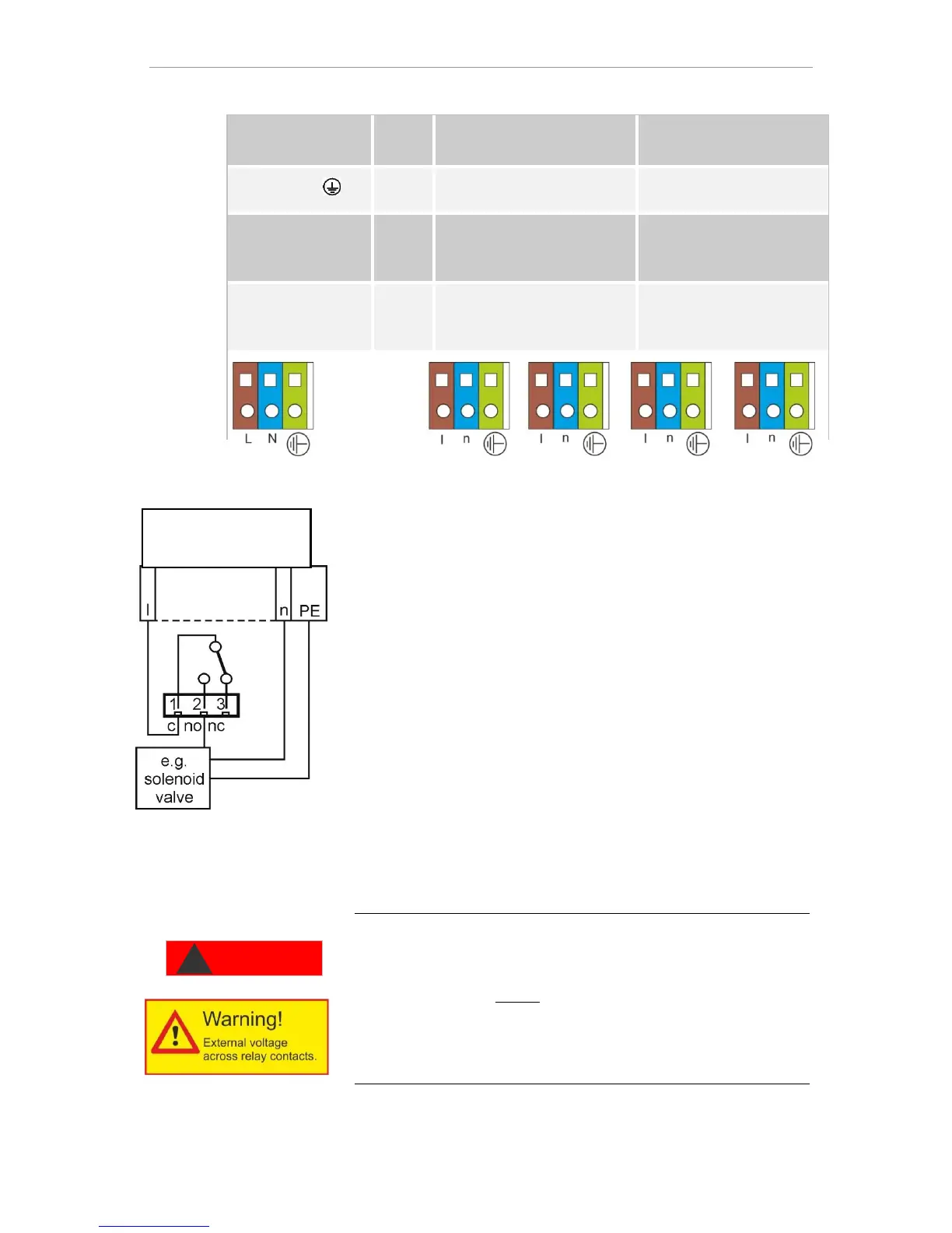
Connect the system components to the output terminals of relays 1
to 4 (e.g. valves)
If the system components require mains power, connect the exter-
nal switched mains voltage (l) to the root contact of the respec-
tive relay (see accompanying connection example for 230 VAC)
Connect the neutral conductor of the system component with one
of the terminals (n)
For components with a protective conductor connection, connect
them to the PE connection.
Ensure that the cores in the terminals are securely in place
(Illustrated position of relays: Device without current, mains: 230 V)
Indicate external voltage on the relay contacts!
If you connect system components that do not operate using the de-
vice voltage, you can apply external voltages to the relay contacts.
This external voltage cannot be switched off via the external mains
switch.
There is a danger of electric shock!
Affix a warning to the device in this case (e.g. a sticker as shown left).