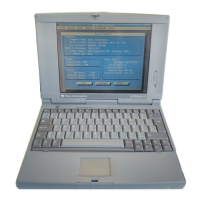
1.6.1 Cover-Display Assembly
The Cover-Display Assembly contains the LCD screen and associated high voltage
power supply and video circuitry. The Cover-Display Assembly contains three
field-replaceable components including:
• LCD Assembly
• Inverter Board
• Slide Pot/Converter Board
The Cover-Display Assembly attaches to the System Base Assembly through four
top mounted screws and six mounting screws on the bottom of the computer.
1.6.2 System Base Assembly
As shown in Figure 1-7, the majority of the notebook’s field replaceable units (FRUs)
are located in the system base assembly. These FRUs include:
• Main Board Assembly
• Hard Disk Drive Assembly
• Memory Board Assembly
• Up to two Dual Inline Memory Modules
• Serial Infra-red Board Assembly
• Floppy Drive Assembly
• Secondary Battery Board Assembly
• Power Supply Board Assembly
• Battery Pack Assembly
• Top Case Assembly
• Touchpad Assembly
• Keyboard Assembly (removed in Figure 1-7 for clarity)
• Battery Board Assembly
General Description 1-11

 Loading...