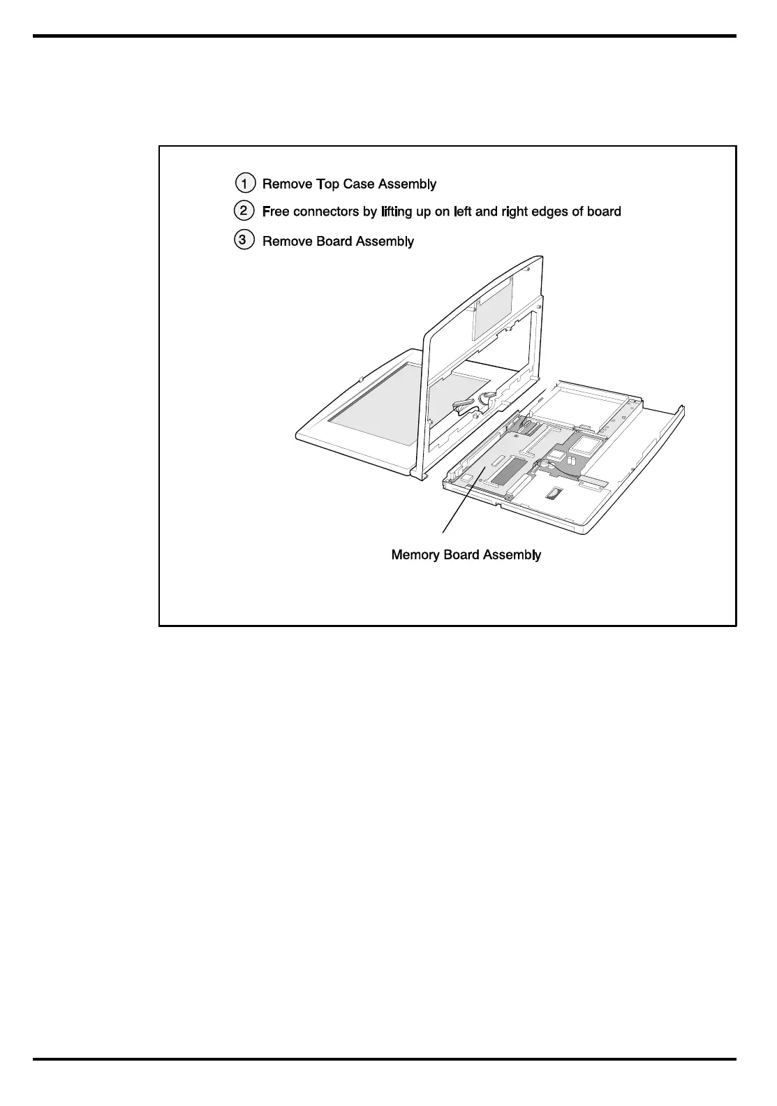
2. Remove the Top Case Assembly as described in Paragraph 6.5.10.
3. Using a plastic stick, lift up on the left and right edges of the board. The board
assembly snaps out. Lift the board out of the unit.
4. Reassembly is the reverse of steps 1 through 3 above.
6.5.16
Removing/Replacing the Main Board
To remove and replace the Main Board Assembly, perform the following procedure:
1. Remove the AC Adapter, Battery Pack, Hard Disk Drive and Floppy Disk Drive
from the unit.
2. Remove the keyboard assembly as described in Paragraph 6.5.5
3. Remove the Heatsink as described in paragraph 6.5.6.
4. Remove the Power Supply Board as described in paragraph 6.5.14.
5. Remove the Memory Board as described in paragraph 6.5.15.
6 Disconnect all interboard cable connectors (SIR Board Connector from J9;
Primary Battery Board Connector from J15, etc.
7 Using a small flat blade screwdriver and apply light pressure in a rocking
motion to remove the hard drive cable connector.
8 Remove the three large Phillips-head screws (one near the 25-pin parallel port and
two screws near the floppy connector. Do not remove the smaller
Figure 6-9 Memory Board Removal
6-16 Field Service
 Loading...