2.01.8
8
0
12
20
25
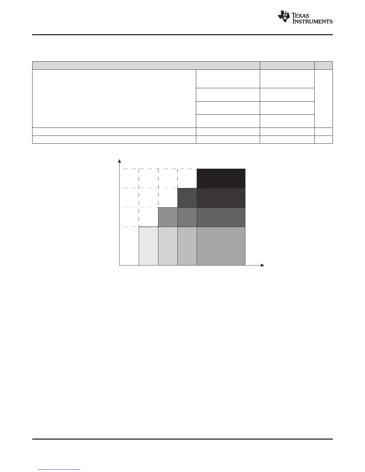
SystemFrequency-MHz
SupplyVoltage-V
ThenumberswithinthefieldsdenotethesupportedPMMCOREVxsettings.
2.2 2.4 3.6
0,1,2,30,1,20,10
1,2,3
1,2
1
2,3
3
2
MSP430F5529
,
MSP430F5528
,
MSP430F5527
,
MSP430F5526
MSP430F5525
,
MSP430F5524
,
MSP430F5522
,
MSP430F5521
MSP430F5519, MSP430F5517, MSP430F5515, MSP430F5514, MSP430F5513
SLAS590M –MARCH 2009–REVISED NOVEMBER 2015
www.ti.com
Recommended Operating Conditions (continued)
Typical values are specified at V
CC
= 3.3 V and T
A
= 25°C (unless otherwise noted)
MIN NOM MAX UNIT
PMMCOREVx = 0,
1.8 V ≤ V
CC
≤ 3.6 V 0 8.0
(default condition)
PMMCOREVx = 1,
0 12.0
Processor frequency (maximum MCLK frequency)
(5)
2.0 V ≤ V
CC
≤ 3.6 V
f
SYSTEM
MHz
(see Figure 5-1)
PMMCOREVx = 2,
0 20.0
2.2 V ≤ V
CC
≤ 3.6 V
PMMCOREVx = 3,
0 25.0
2.4 V ≤ V
CC
≤ 3.6 V
f
SYSTEM_USB
Minimum processor frequency for USB operation 1.5 MHz
USB_wait Wait state cycles during USB operation 16 cycles
(5) Modules may have a different maximum input clock specification. See the specification of the respective module in this data sheet.
Figure 5-1. Maximum System Frequency
20 Specifications Copyright © 2009–2015, Texas Instruments Incorporated
Submit Documentation Feedback
Product Folder Links: MSP430F5529 MSP430F5528 MSP430F5527 MSP430F5526 MSP430F5525 MSP430F5524
MSP430F5522 MSP430F5521 MSP430F5519 MSP430F5517 MSP430F5515 MSP430F5514 MSP430F5513