MSP430F5529
,
MSP430F5528
,
MSP430F5527
,
MSP430F5526
MSP430F5525
,
MSP430F5524
,
MSP430F5522
,
MSP430F5521
MSP430F5519, MSP430F5517, MSP430F5515, MSP430F5514, MSP430F5513
SLAS590M –MARCH 2009–REVISED NOVEMBER 2015
www.ti.com
6.5 Bootstrap Loader (BSL)
The BSL enables users to program the flash memory or RAM using various serial interfaces. Access to
the device memory by the BSL is protected by an user-defined password. For further details on interfacing
to development tools and device programmers, see the MSP430 Hardware Tools User's Guide
(SLAU278). For complete description of the features of the BSL and its implementation, see the MSP430
Programming Via the Bootstrap Loader User's Guide (SLAU319).
6.5.1 USB BSL
All devices come preprogrammed with the USB BSL. Use of the USB BSL requires external access to the
six pins shown in Table 6-3. In addition to these pins, the application must support external components
necessary for normal USB operation; for example, the proper crystal on XT2IN and XT2OUT, proper
decoupling, and so on.
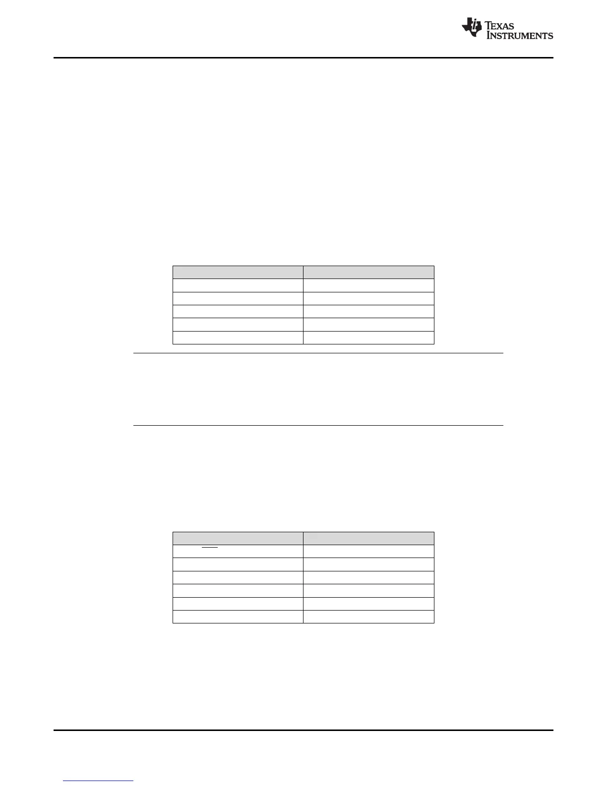
Table 6-3. USB BSL Pin Requirements and Functions
DEVICE SIGNAL BSL FUNCTION
PU.0/DP USB data terminal DP
PU.1/DM USB data terminal DM
PUR USB pullup resistor terminal
VBUS USB bus power supply
VSSU USB ground supply
NOTE
The default USB BSL evaluates the logic level of the PUR pin after a BOR reset. If the PUR
pin is pulled high externally, then the BSL is invoked. Therefore, unless the application is
invoking the BSL, it is important to keep PUR pulled low after a BOR reset, even if BSL or
USB is never used. TI recommends applying a 1-MΩ resistor to ground.
6.5.2 UART BSL
A UART BSL is also available that can be programmed by the user into the BSL memory by replacing the
preprogrammed, factory supplied, USB BSL. Use of the UART BSL requires external access to the six
pins shown in Table 6-4.
Table 6-4. UART BSL Pin Requirements and Functions
DEVICE SIGNAL BSL FUNCTION
RST/NMI/SBWTDIO Entry sequence signal
TEST/SBWTCK Entry sequence signal
P1.1 Data transmit
P1.2 Data receive
VCC Power supply
VSS Ground supply
54 Detailed Description Copyright © 2009–2015, Texas Instruments Incorporated
Submit Documentation Feedback
Product Folder Links: MSP430F5529 MSP430F5528 MSP430F5527 MSP430F5526 MSP430F5525 MSP430F5524
MSP430F5522 MSP430F5521 MSP430F5519 MSP430F5517 MSP430F5515 MSP430F5514 MSP430F5513