MSP430F5529
,
MSP430F5528
,
MSP430F5527
,
MSP430F5526
MSP430F5525
,
MSP430F5524
,
MSP430F5522
,
MSP430F5521
MSP430F5519, MSP430F5517, MSP430F5515, MSP430F5514, MSP430F5513
SLAS590M –MARCH 2009–REVISED NOVEMBER 2015
www.ti.com
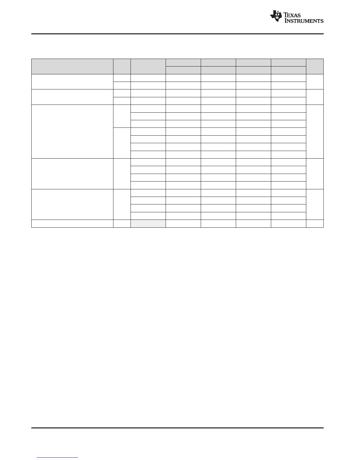
5.5 Low-Power Mode Supply Currents (Into V
CC
) Excluding External Current
over recommended ranges of supply voltage and operating free-air temperature (unless otherwise noted)
(1) (2)
–40°C 25°C 60°C 85°C
PARAMETER V
CC
PMMCOREVx UNIT
TYP MAX TYP MAX TYP MAX TYP MAX
2.2 V 0 73 77 85 80 85 97
I
LPM0,1MHz
Low-power mode 0
(3)(4)
µA
3.0 V 3 79 83 92 88 95 105
2.2 V 0 6.5 6.5 12 10 11 17
I
LPM2
Low-power mode 2
(5)(4)
µA
3.0 V 3 7.0 7.0 13 11 12 18
0 1.60 1.90 2.6 5.6
2.2 V 1 1.65 2.00 2.7 5.9
2 1.75 2.15 2.9 6.1
Low-power mode 3,
I
LPM3,XT1LF
0 1.8 2.1 2.9 2.8 5.8 8.3 µA
crystal mode
(6)(4)
1 1.9 2.3 2.9 6.1
3.0 V
2 2.0 2.4 3.0 6.3
3 2.0 2.5 3.9 3.1 6.4 9.3
0 1.1 1.4 2.7 1.9 4.9 7.4
1 1.1 1.4 2.0 5.2
Low-power mode 3,
I
LPM3,VLO
3.0 V µA
VLO mode
(7)(4)
2 1.2 1.5 2.1 5.3
3 1.3 1.6 3.0 2.2 5.4 8.5
0 0.9 1.1 1.5 1.8 4.8 7.3
1 1.1 1.2 2.0 5.1
I
LPM4
Low-power mode 4
(8)(4)
3.0 V µA
2 1.2 1.2 2.1 5.2
3 1.3 1.3 1.6 2.2 5.3 8.1
I
LPM4.5
Low-power mode 4.5
(9)
3.0 V 0.15 0.18 0.35 0.26 0.5 1.0 µA
(1) All inputs are tied to 0 V or to V
CC
. Outputs do not source or sink any current.
(2) The currents are characterized with a Micro Crystal MS1V-T1K crystal with a load capacitance of 12.5 pF. The internal and external load
capacitance are chosen to closely match the required 12.5 pF.
(3) Current for watchdog timer clocked by SMCLK included. ACLK = low frequency crystal operation (XTS = 0, XT1DRIVEx = 0).
CPUOFF = 1, SCG0 = 0, SCG1 = 0, OSCOFF = 0 (LPM0); f
ACLK
= 32768 Hz, f
MCLK
= 0 MHz, f
SMCLK
= f
DCO
= 1 MHz
USB disabled (VUSBEN = 0, SLDOEN = 0).
(4) Current for brownout, high-side supervisor (SVS
H
) normal mode included. Low-side supervisor and monitor disabled (SVS
L
, SVM
L
).
High-side monitor disabled (SVM
H
). RAM retention enabled.
(5) Current for watchdog timer and RTC clocked by ACLK included. ACLK = low frequency crystal operation (XTS = 0, XT1DRIVEx = 0).
CPUOFF = 1, SCG0 = 0, SCG1 = 1, OSCOFF = 0 (LPM2); f
ACLK
= 32768 Hz, f
MCLK
= 0 MHz, f
SMCLK
= f
DCO
= 0 MHz; DCO setting = 1
MHz operation, DCO bias generator enabled.
USB disabled (VUSBEN = 0, SLDOEN = 0)
(6) Current for watchdog timer and RTC clocked by ACLK included. ACLK = low frequency crystal operation (XTS = 0, XT1DRIVEx = 0).
CPUOFF = 1, SCG0 = 1, SCG1 = 1, OSCOFF = 0 (LPM3); f
ACLK
= 32768 Hz, f
MCLK
= f
SMCLK
= f
DCO
= 0 MHz
USB disabled (VUSBEN = 0, SLDOEN = 0)
(7) Current for watchdog timer and RTC clocked by ACLK included. ACLK = VLO.
CPUOFF = 1, SCG0 = 1, SCG1 = 1, OSCOFF = 0 (LPM3); f
ACLK
= f
VLO
, f
MCLK
= f
SMCLK
= f
DCO
= 0 MHz
USB disabled (VUSBEN = 0, SLDOEN = 0)
(8) CPUOFF = 1, SCG0 = 1, SCG1 = 1, OSCOFF = 1 (LPM4); f
DCO
= f
ACLK
= f
MCLK
= f
SMCLK
= 0 MHz
USB disabled (VUSBEN = 0, SLDOEN = 0)
(9) Internal regulator disabled. No data retention.
CPUOFF = 1, SCG0 = 1, SCG1 = 1, OSCOFF = 1, PMMREGOFF = 1 (LPM4.5); f
DCO
= f
ACLK
= f
MCLK
= f
SMCLK
= 0 MHz
22 Specifications Copyright © 2009–2015, Texas Instruments Incorporated
Submit Documentation Feedback
Product Folder Links: MSP430F5529 MSP430F5528 MSP430F5527 MSP430F5526 MSP430F5525 MSP430F5524
MSP430F5522 MSP430F5521 MSP430F5519 MSP430F5517 MSP430F5515 MSP430F5514 MSP430F5513