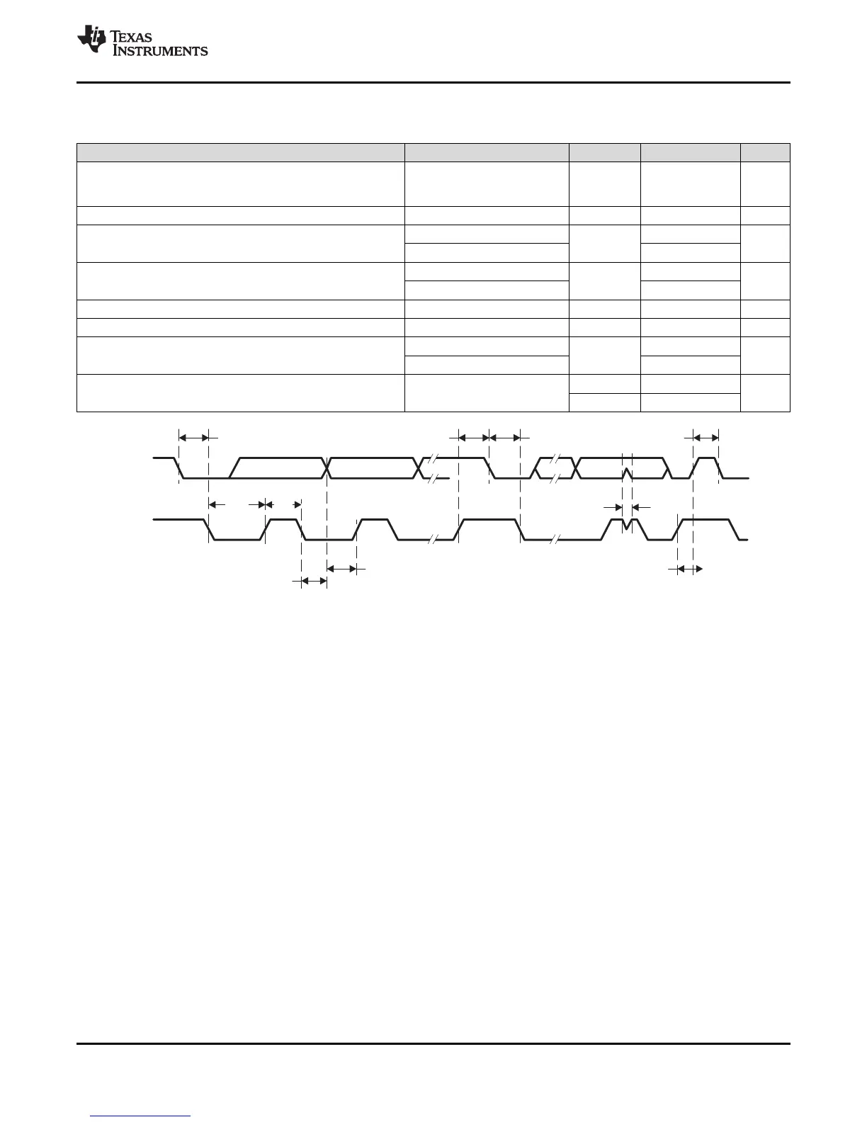
SDA
SCL
t
HD,DAT
t
SU,DAT
t
HD,STA
t
HIGH
t
LOW
t
BUF
t
HD,STA
t
SU,STA
t
SP
t
SU,STO
MSP430F5529
,
MSP430F5528
,
MSP430F5527
,
MSP430F5526
MSP430F5525
,
MSP430F5524
,
MSP430F5522
,
MSP430F5521
MSP430F5519, MSP430F5517, MSP430F5515, MSP430F5514, MSP430F5513
www.ti.com
SLAS590M –MARCH 2009–REVISED NOVEMBER 2015
5.34 USCI (I
2
C Mode)
over recommended ranges of supply voltage and operating free-air temperature (unless otherwise noted) (see Figure 5-15)
PARAMETER TEST CONDITIONS V
CC
MIN MAX UNIT
Internal: SMCLK, ACLK
f
USCI
USCI input clock frequency External: UCLK f
SYSTEM
MHz
Duty cycle = 50% ± 10%
f
SCL
SCL clock frequency 2.2 V, 3 V 0 400 kHz
f
SCL
≤ 100 kHz 4.0
t
HD,STA
Hold time (repeated) START 2.2 V, 3 V µs
f
SCL
> 100 kHz 0.6
f
SCL
≤ 100 kHz 4.7
t
SU,STA
Setup time for a repeated START 2.2 V, 3 V µs
f
SCL
> 100 kHz 0.6
t
HD,DAT
Data hold time 2.2 V, 3 V 0 ns
t
SU,DAT
Data setup time 2.2 V, 3 V 250 ns
f
SCL
≤ 100 kHz 4.0
t
SU,STO
Setup time for STOP 2.2 V, 3 V µs
f
SCL
> 100 kHz 0.6
2.2 V 50 600
Pulse duration of spikes suppressed by input
t
SP
ns
filter
3 V 50 600
Figure 5-15. I
2
C Mode Timing
Copyright © 2009–2015, Texas Instruments Incorporated Specifications 39
Submit Documentation Feedback
Product Folder Links: MSP430F5529 MSP430F5528 MSP430F5527 MSP430F5526 MSP430F5525 MSP430F5524
MSP430F5522 MSP430F5521 MSP430F5519 MSP430F5517 MSP430F5515 MSP430F5514 MSP430F5513