RM46L852
SPNS185 –SEPTEMBER 2012
www.ti.com
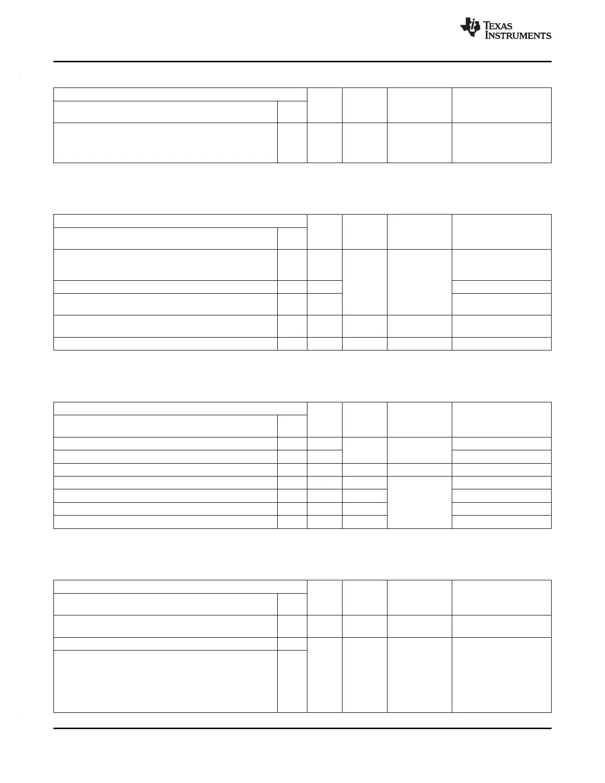
Table 2-18. PGE System Module Interface (continued)
Terminal Signal Default Pull Type Description
Type Pull State
Signal Name 144
PGE
nERROR 117 I/O Pull Down 20uA ESM Error Signal
Indicates error of high
severity. See
Section 4.18.
2.3.1.16 Clock Inputs and Outputs
Table 2-19. PGE Clock Inputs and Outputs
Terminal Signal Default Pull Type Description
Type Pull State
Signal Name 144
PGE
OSCIN 18 Input - - From external
crystal/resonator, or
external clock input
KELVIN_GND 19 Input Kelvin ground for oscillator
OSCOUT 20 Output To external
crystal/resonator
ECLK 119 I/O Pull Down Programmable, External prescaled clock
20uA output, or GIO.
GIOA[5]/EXTCLKIN/EPWM1A /N2HET1_PIN_nDIS 14 Input Pull Down 20uA External clock input #1
2.3.1.17 Test and Debug Modules Interface
Table 2-20. PGE Test and Debug Modules Interface
Terminal Signal Default Pull Type Description
Type Pull State
Signal Name 144
PGE
TEST 34 Input Pull Down Fixed, 100uA Test enable
nTRST 109 Input JTAG test hardware reset
RTCK 113 Output - - JTAG return test clock
TCK 112 Input Pull Down Fixed, 100uA JTAG test clock
TDI 110 Input Pull Up JTAG test data in
TDO 111 Output Pull Down JTAG test data out
TMS 108 Input Pull Up JTAG test select
2.3.1.18 Flash Supply and Test Pads
Table 2-21. PGE Flash Supply and Test Pads
Terminal Signal Default Pull Type Description
Type Pull State
Signal Name 144
PGE
VCCP 134 3.3V - - Flash pump supply
Power
FLTP1 7 - - - Flash test pads. These
terminals are reserved for
FLTP2 8
TI use only. For proper
operation these terminals
must connect only to a
test pad or not be
connected at all [no
connect (NC)].
22 Device Package and Terminal Functions Copyright © 2012, Texas Instruments Incorporated
Submit Documentation Feedback
 Loading...


