108
TMS320C6748
SPRS590G –JUNE 2009–REVISED JANUARY 2017
www.ti.com
Submit Documentation Feedback
Product Folder Links: TMS320C6748
Peripheral Information and Electrical Specifications Copyright © 2009–2017, Texas Instruments Incorporated
(1) The shaded cells indicate configurations that are possible on the EMIFA interface but as of this writing SDRAM memories capable of
supporting these densities are not available in the market.
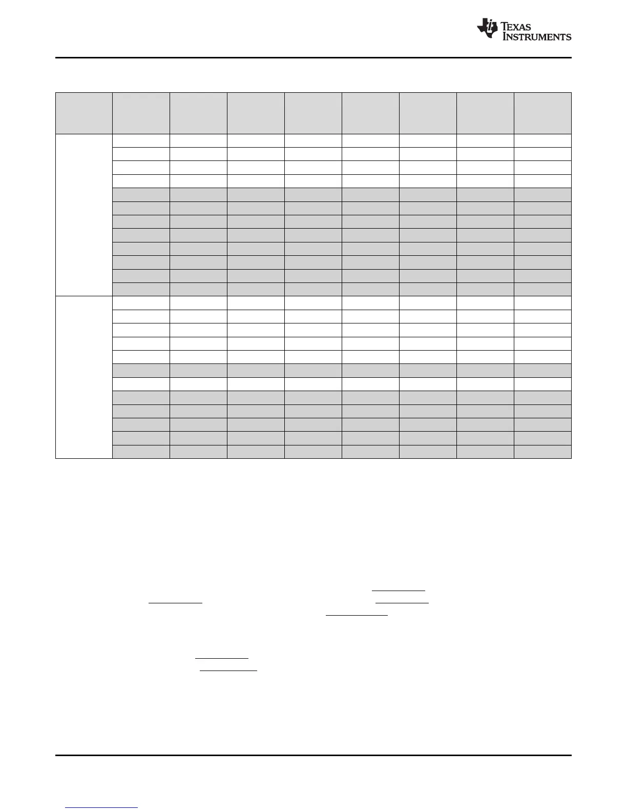
Table 6-17. EMIFA Supported SDRAM Configurations
(1)
SDRAM
Memory
Data Bus
Width (bits)
Number of
Memories
EMIFA Data
Bus Size
(bits)
Rows Columns Banks
Total
Memory
(Mbits)
Total
Memory
(Mbytes)
Memory
Density
(Mbits)
1 16 16 8 1 256 32 256
1 16 16 8 2 512 64 512
1 16 16 8 4 1024 128 1024
1 16 16 9 1 512 64 512
1 16 16 9 2 1024 128 1024
16 1 16 16 9 4 2048 256 2048
1 16 16 10 1 1024 128 1024
1 16 16 10 2 2048 256 2048
1 16 16 10 4 4096 512 4096
1 16 16 11 1 2048 256 2048
1 16 16 11 2 4096 512 4096
1 16 15 11 4 4096 512 4096
2 16 16 8 1 256 32 128
2 16 16 8 2 512 64 256
2 16 16 8 4 1024 128 512
2 16 16 9 1 512 64 256
2 16 16 9 2 1024 128 512
8 2 16 16 9 4 2048 256 1024
2 16 16 10 1 1024 128 512
2 16 16 10 2 2048 256 1024
2 16 16 10 4 4096 512 2048
2 16 16 11 1 2048 256 1024
2 16 16 11 2 4096 512 2048
2 16 15 11 4 4096 512 2048
6.10.3 EMIFA SDRAM Loading Limitations
EMIFA supports SDRAM up to 100 MHz with up to two SDRAM or asynchronous memory loads.
Additional loads will limit the SDRAM operation to lower speeds and the maximum speed should be
confirmed by board simulation using IBIS models.
6.10.4 EMIFA Connection Examples
Figure 6-10 illustrates an example of how SDRAM, NOR, and NAND flash devices might be connected to
EMIFA simultaneously. The SDRAM chip select must be EMA_CS[0]. Note that the NOR flash is
connected to EMA_CS[2] and the NAND flash is connected to EMA_CS[3] in this example. Note that any
type of asynchronous memory may be connected to EMA_CS[5:2].
The on-chip bootloader makes some assumptions on which chip select the contains the boot image, and
this depends on the boot mode. For NOR boot mode; the on-chip bootloader requires that the image be
stored in NOR flash on EMA_CS[2]. For NAND boot mode, the bootloader requires that the boot image is
stored in NAND flash on EMA_CS[3]. It is always possible to have the image span multiple chip selects,
but this must be supported by second stage boot code stored in the external flash.