114
TMS320C6748
SPRS590G –JUNE 2009–REVISED JANUARY 2017
www.ti.com
Submit Documentation Feedback
Product Folder Links: TMS320C6748
Peripheral Information and Electrical Specifications Copyright © 2009–2017, Texas Instruments Incorporated
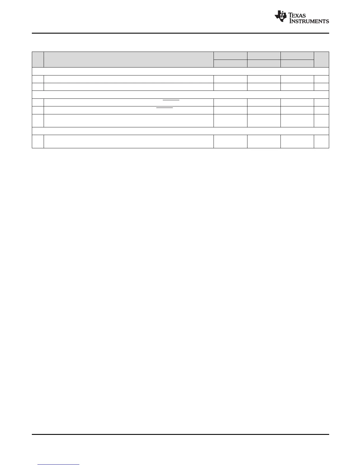
(1) E = EMA_CLK period or in ns. EMA_CLK is selected either as SYSCLK3 or the PLL0 output clock divided by 4.5. As an example, when
SYSCLK3 is selected and set to 100MHz, E=10ns
(2) Setup before end of STROBE phase (if no extended wait states are inserted) by which EM_WAIT must be asserted to add extended
wait states. Figure 6-16 and Figure 6-17 describe EMIF transactions that include extended wait states inserted during the STROBE
phase. However, cycles inserted as part of this extended wait period should not be counted; the 4E requirement is to the start of where
the HOLD phase would begin if there were no extended wait cycles.
Table 6-21. Timing Requirements for EMIFA Asynchronous Memory Interface
(1)
NO.
1.3V, 1.2V 1.1V 1.0V
UNIT
MIN MAX MIN MAX MIN MAX
READS and WRITES
E t
c(CLK)
Cycle time, EMIFA module clock 6.75 13.33 20 ns
2 t
w(EM_WAIT)
Pulse duration, EM_WAIT assertion and deassertion 2E 2E 2E ns
READS
12 t
su(EMDV-EMOEH)
Setup time, EM_D[15:0] valid before EM_OE high 3 5 7 ns
13 t
h(EMOEH-EMDIV)
Hold time, EM_D[15:0] valid after EM_OE high 0 0 0 ns
14
t
su (EMOEL-
EMWAIT)
Setup Time, EM_WAIT asserted before end of Strobe
Phase
(2)
4E+3 4E+3 4E+3 ns
WRITES
28
t
su (EMWEL-
EMWAIT)
Setup Time, EM_WAIT asserted before end of Strobe
Phase
(2)
4E+3 4E+3 4E+3 ns