126
TMS320C6748
SPRS590G –JUNE 2009–REVISED JANUARY 2017
www.ti.com
Submit Documentation Feedback
Product Folder Links: TMS320C6748
Peripheral Information and Electrical Specifications Copyright © 2009–2017, Texas Instruments Incorporated
(1) These devices should be placed near the device they are bypassing, but preference should be given to the placement of the high-speed
(HS) bypass caps.
(2) Only used on dual-memory systems.
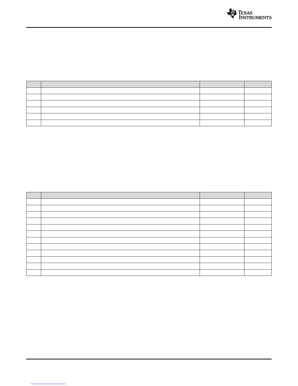
6.11.3.6 Bulk Bypass Capacitors
Bulk bypass capacitors are required for moderate speed bypassing of the DDR2/mDDR and other
circuitry. Table 6-29 contains the minimum numbers and capacitance required for the bulk bypass
capacitors. Note that this table only covers the bypass needs of the DSP and DDR2/mDDR interfaces.
Additional bulk bypass capacitance may be needed for other circuitry.
Table 6-29. Bulk Bypass Capacitors
NO. PARAMETER MIN MAX UNIT
1 DDR_DVDD18 Supply Bulk Bypass Capacitor Count
(1)
3 Devices
2 DDR_DVDD18 Supply Bulk Bypass Total Capacitance 30 μF
3 DDR#1 Bulk Bypass Capacitor Count
(1)
1 Devices
4 DDR#1 Bulk Bypass Total Capacitance 22 μF
5 DDR#2 Bulk Bypass Capacitor Count
(1)(2)
1 Devices
6 DDR#2 Bulk Bypass Total Capacitance
(2)
22 μF
(1) LxW, 10 mil units, i.e., a 0402 is a 40x20 mil surface mount capacitor
(2) An additional HS bypass capacitor can share the connection vias only if it is mounted on the opposite side of the board.
(3) These devices should be placed as close as possible to the device being bypassed.
(4) Only used on dual-memory systems.
6.11.3.7 High-Speed Bypass Capacitors
High-speed (HS) bypass capacitors are critical for proper DDR2/mDDR interface operation. It is
particularly important to minimize the parasitic series inductance of the HS bypass cap, DSP/DDR2/mDDR
power, and DSP/DDR2/mDDR ground connections. Table 6-30 contains the specification for the HS
bypass capacitors as well as for the power connections on the PCB.
Table 6-30. High-Speed Bypass Capacitors
NO. PARAMETER MIN MAX UNIT
1 HS Bypass Capacitor Package Size
(1)
0402 10 Mils
2 Distance from HS bypass capacitor to device being bypassed 250 Mils
3 Number of connection vias for each HS bypass capacitor 2
(2)
Vias
4 Trace length from bypass capacitor contact to connection via 1 30 Mils
5 Number of connection vias for each DDR2/mDDR device power or ground balls 1 Vias
6 Trace length from DDR2/mDDR device power ball to connection via 35 Mils
7 DDR_DVDD18 Supply HS Bypass Capacitor Count
(3)
10 Devices
8 DDR_DVDD18 Supply HS Bypass Capacitor Total Capacitance 0.6 μF
9 DDR#1 HS Bypass Capacitor Count
(3)
8 Devices
10 DDR#1 HS Bypass Capacitor Total Capacitance 0.4 μF
11 DDR#2 HS Bypass Capacitor Count
(3)(4)
8 Devices
12 DDR#2 HS Bypass Capacitor Total Capacitance
(4)
0.4 μF
 Loading...


