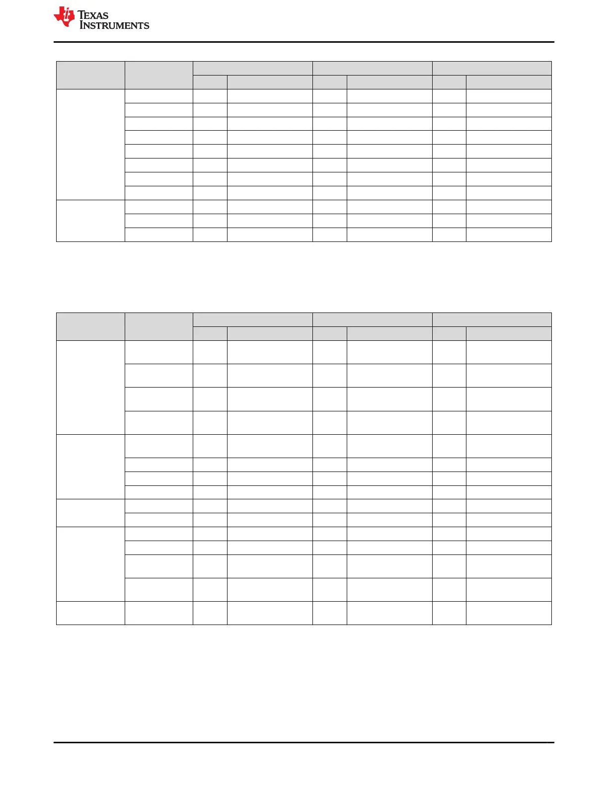
Table 5-6. GPIO NVM Settings (continued)
Register Name Field Name
TPS65941120-Q1 TPS65941421-Q1 LP876411B5-Q1
Value Description Value Description Value Description
GPIO_OUT_1 GPIO1_OUT 0x0 Low 0x0 Low 0x0 Low
GPIO2_OUT 0x0 Low 0x0 Low 0x0 Low
GPIO3_OUT 0x0 Low 0x0 Low 0x0 Low
GPIO4_OUT 0x0 Low 0x0 Low 0x0 Low
GPIO5_OUT 0x0 Low 0x0 Low 0x0 Low
GPIO6_OUT 0x0 Low 0x0 Low 0x0 Low
GPIO7_OUT 0x0 Low 0x0 Low 0x0 Low
GPIO8_OUT 0x0 Low 0x0 Low 0x0 Low
GPIO_OUT_2 GPIO9_OUT 0x0 Low 0x0 Low 0x0 Low
GPIO10_OUT 0x0 Low 0x0 Low 0x0 Low
GPIO11_OUT 0x0 Low 0x0 Low
5.7 Finite State Machine (FSM) Settings
These settings describe how the PMIC output rails are assigned to various system-level states. Also, the default
trigger for each system-level state is described. All these settings can be changed though I
2
C after startup.
Table 5-7. FSM NVM Settings
Register Name Field Name
TPS65941120-Q1 TPS65941421-Q1 LP876411B5-Q1
Value Description Value Description Value Description
RAIL_SEL_1 BUCK1_GRP_SE
L
0x2 SOC rail group 0x2 SOC rail group 0x2 SOC rail group
BUCK2_GRP_SE
L
0x2 SOC rail group 0x0 No group assigned 0x2 SOC rail group
BUCK3_GRP_SE
L
0x1 MCU rail group 0x2 SOC rail group 0x0 No group assigned
BUCK4_GRP_SE
L
0x0 No group assigned 0x1 MCU rail group 0x0 No group assigned
RAIL_SEL_2 BUCK5_GRP_SE
L
0x1 MCU rail group 0x2 SOC rail group
LDO1_GRP_SEL 0x1 MCU rail group 0x2 SOC rail group
LDO2_GRP_SEL 0x1 MCU rail group 0x1 MCU rail group
LDO3_GRP_SEL 0x1 MCU rail group 0x2 SOC rail group
RAIL_SEL_3 LDO4_GRP_SEL 0x1 MCU rail group 0x2 SOC rail group
VCCA_GRP_SEL 0x1 MCU rail group 0x1 MCU rail group 0x1 MCU rail group
FSM_TRIG_SEL
_1
MCU_RAIL_TRIG 0x2 MCU power error 0x2 MCU power error 0x2 MCU power error
SOC_RAIL_TRIG 0x3 SOC power error 0x3 SOC power error 0x3 SOC power error
OTHER_RAIL_T
RIG
0x3 SOC power error 0x3 SOC power error 0x3 SOC power error
SEVERE_ERR_T
RIG
0x0 Immediate shutdown 0x0 Immediate shutdown 0x0 Immediate shutdown
FSM_TRIG_SEL
_2
MODERATE_ER
R_TRIG
0x1 Orderly shutdown 0x1 Orderly shutdown 0x1 Orderly shutdown
5.8 Interrupt Settings
These settings detail the default configurations for what is monitored by nINT pin. All these settings can be
changed though I
2
C after startup.
www.ti.com Static NVM Settings
SLVUCJ9 – FEBRUARY 2023
Submit Document Feedback
TPS65941120-Q1, TPS65941421-Q1 and LP876411B5-Q1 PMIC User Guide
for J721S2, PDN-0A
23
Copyright © 2023 Texas Instruments Incorporated
 Loading...


