bit is set and VCCA OV and UV masks are cleared (which are set in the static configurations, Table 5-8). After
these instructions are executed the PMICs wait for a valid ON Request before entering the ACTIVE state. The
definition for each power state is described below:
STANDBY The PMICs are powered by a valid supply on the system power rail (VCCA > VCCA_UV). All
device resources are powered down in the STANDBY state. EN_DRV is forced low in this state. The
processor is in the Off state, no voltage domains are energized. Refer to the Section 6.3.2 sequence
description.
The STANDBY state is also entered when an error occurs and the PMIC transitions out of the PFSM
mission states and into the FSM states. When the device returns from the FSM state the to PFSM
the first state is represented by STANDBY with all of the resources powered down and EN_DRV
forced low. The sequence Section 6.3.1 is performed before the PMIC leaves the PFSM and enters
the FSM state SAFE_RECOVERY.
ACTIVE The PMICs are powered by a valid supply. The PMICs are fully functional and supply power to
all PDN loads. The processor has completed a recommended power up sequence with all voltage
domains energized in both MCU and Main processor sections. Refer to the Section 6.3.8 sequence
description.
Retention The PMICs are powered by a valid supply. When the PMICs I2C_7 triggers are set (DDR
Retention), 2 SoC voltage domains (vdds_ddr_bias and vdds_ddr) remain energized, in addition
to the LPDDR4, while all other domains are off to minimize total system power. When the PMICs
I2C_5 triggers are set (GPIO Retention), 4 voltage domains (vdd_mcu_wake1, vddshv0_mcu,
vdd_wake0, vddshv2) remain energized, while all other domains are off to minimize total system
power. EN_DRV is forced low in this state. Refer to the Section 6.3.9 sequence description.
6.2 PFSM Triggers
As shown in Figure 6-1, there are various triggers that can enable a state transition between configured states.
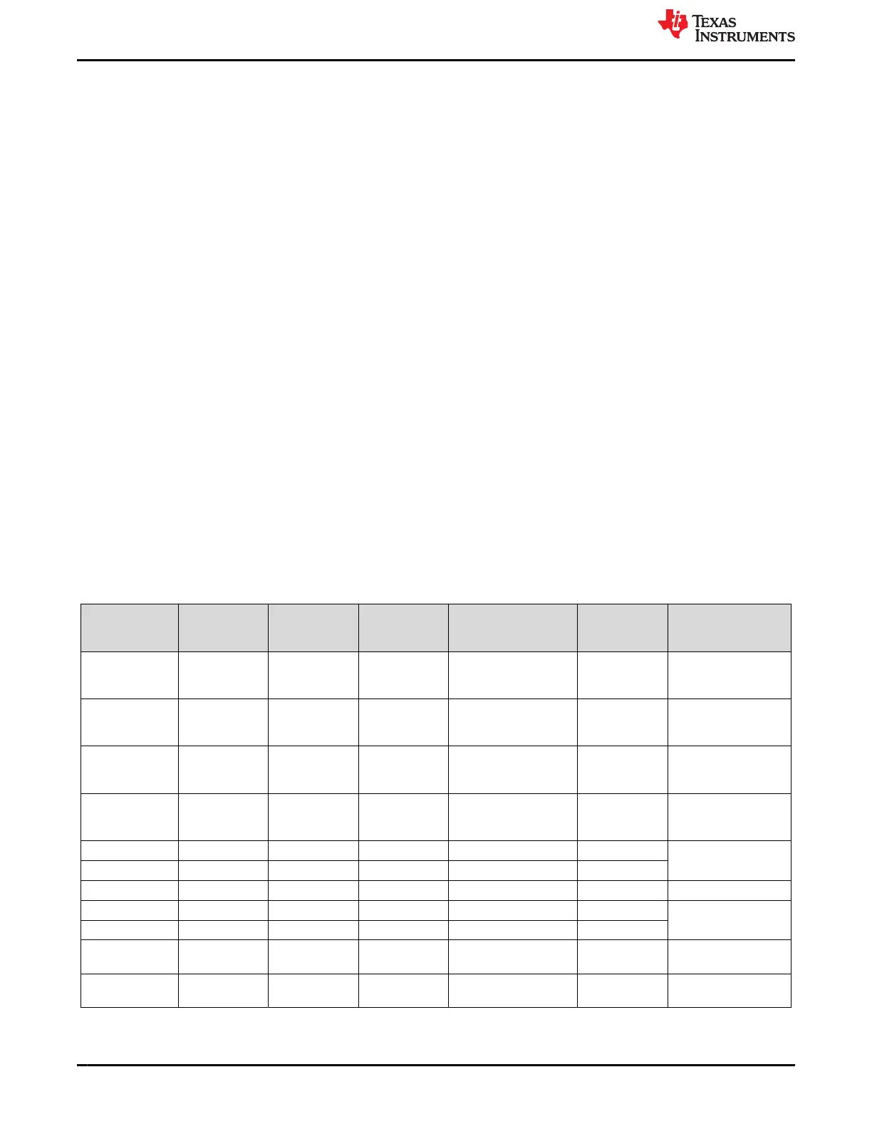
Table 6-1 describes each trigger and its associated state transition from highest priority (Immediate Shutdown)
to lowest priority (I2C_3). Active triggers of higher priority block triggers of lower priority and the associated
sequence.
Table 6-1. State Transition Triggers
Trigger Priority (ID)
Immediate
(IMM)
REENTERANT PFSM Current State
PFSM
Destination
State
Power Sequence or
Function Executed
Immediate
Shutdown
(8)
1 True False
STANDBY, ACTIVE,
MCU ONLY, Suspend-
to-RAM
SAFE
(1)
TO_SAFE_SEVERE
MCU Power Error 2 True False
STANDBY, ACTIVE,
MCU ONLY, Suspend-
to-RAM
SAFE
(1)
TO_SAFE
Orderly
Shutdown
(8)
3 True False
STANDBY, ACTIVE,
MCU ONLY, Suspend-
to-RAM
SAFE
(1)
TO_SAFE_ORDERLY
OFF Request 5
(10)
False False
STANDBY, ACTIVE,
MCU ONLY, Suspend-
to-RAM
STANDBY
(2)
TO_STANDBY
WDOG Error 6 False True ACTIVE ACTIVE
ACTIVE_TO_WARM
ESM MCU Error 7 False True ACTIVE ACTIVE
ESM SOC Error 8 False True ACTIVE ACTIVE ESM_SOC_ERROR
WDOG Error 9 False True MCU ONLY MCU ONLY MCU_TO_WARM
ESM MCU Error 10 False True MCU ONLY MCU ONLY
SOC Power Error 11 False False ACTIVE SOC Power
Error
PWR_SOC_ERR
I2C_1 bit is
high
(3)
12 False True ACTIVE, MCU ONLY
No State
Change
Execute RUNTIME
BIST
Pre-Configurable Finite State Machine (PFSM) Settings www.ti.com
34 TPS65941120-Q1, TPS65941421-Q1 and LP876411B5-Q1 PMIC User Guide
for J721S2, PDN-0A
SLVUCJ9 – FEBRUARY 2023
Submit Document Feedback
Copyright © 2023 Texas Instruments Incorporated
 Loading...


