Table 5-8. Interrupt NVM Settings (continued)
Register Name Field Name
TPS65941120-Q1 TPS65941421-Q1 LP876411B5-Q1
Value Description Value Description Value Description
GENERAL_REG
_1
PFSM_ERR_MA
SK
0x0 Interrupt generated 0x0 Interrupt generated 0x0 Interrupt generated
(1) The VCCA_OV_MASK and VCCA_UV_MASK are cleared in both PMICs after the completing BOOT_BIST but before starting the
sequence, Section 6.3.8.
5.9 POWERGOOD Settings
These settings detail the default configurations for what is monitored by PGOOD pin. All these settings can be
changed though I
2
C after startup.
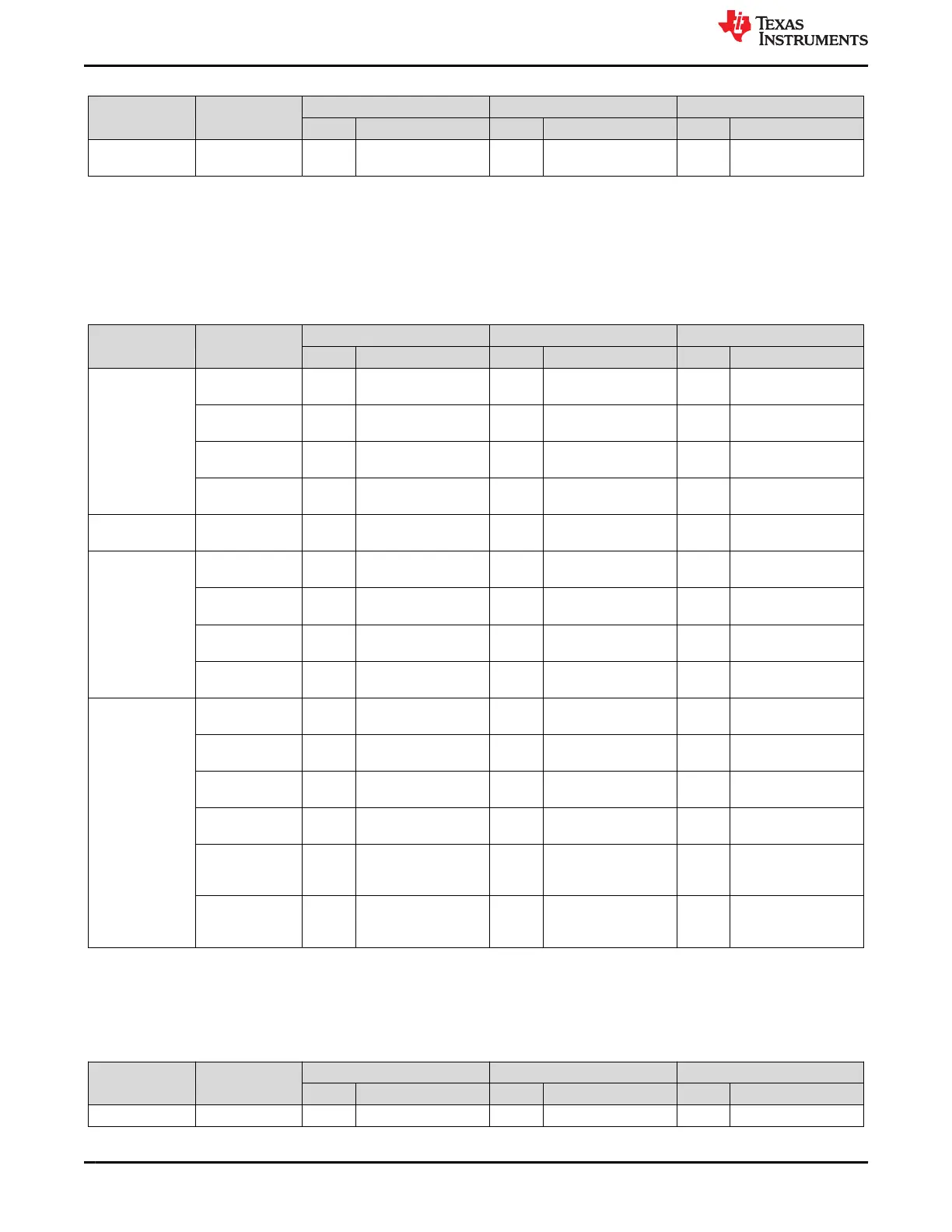
Table 5-9. POWERGOOD NVM Settings
Register Name Field Name
TPS65941120-Q1 TPS65941421-Q1 LP876411B5-Q1
Value Description Value Description Value Description
PGOOD_SEL_1 PGOOD_SEL_B
UCK1
0x0 Masked 0x0 Masked 0x0 Masked
PGOOD_SEL_B
UCK2
0x0 Masked 0x0 Masked 0x0 Masked
PGOOD_SEL_B
UCK3
0x0 Masked 0x0 Masked 0x0 Masked
PGOOD_SEL_B
UCK4
0x0 Masked 0x0 Masked 0x0 Masked
PGOOD_SEL_2 PGOOD_SEL_B
UCK5
0x0 Masked 0x0 Masked
PGOOD_SEL_3 PGOOD_SEL_LD
O1
0x0 Masked 0x0 Masked
PGOOD_SEL_LD
O2
0x0 Masked 0x0 Masked
PGOOD_SEL_LD
O3
0x0 Masked 0x0 Masked
PGOOD_SEL_LD
O4
0x0 Masked 0x0 Masked
PGOOD_SEL_4 PGOOD_SEL_V
CCA
0x0 Masked 0x0 Masked 0x0 Masked
PGOOD_SEL_T
DIE_WARN
0x0 Masked 0x0 Masked 0x0 Masked
PGOOD_SEL_N
RSTOUT
0x0 Masked 0x0 Masked 0x0 Masked
PGOOD_SEL_N
RSTOUT_ SOC
0x0 Masked 0x0 Masked 0x0 Masked
PGOOD_POL 0x0 PGOOD signal is high
when monitored inputs
are valid
0x0 PGOOD signal is high
when monitored inputs
are valid
0x0 PGOOD signal is high
when monitored inputs
are valid
PGOOD_WINDO
W
0x1 Both undervoltage
and overvoltage are
monitored
0x1 Both undervoltage
and overvoltage are
monitored
0x0 Only undervoltage is
monitored
5.10 Miscellaneous Settings
These settings detail the default configurations of additional settings, such as spread spectrum, BUCK
frequency, and LDO timeout. All these settings can be changed though I
2
C after startup.
Table 5-10. Miscellaneous NVM Settings
Register Name Field Name
TPS65941120-Q1 TPS65941421-Q1 LP876411B5-Q1
Value Description Value Description Value Description
PLL_CTRL EXT_CLK_FREQ 0x0 1.1 MHz 0x0 1.1 MHz 0x0 1.1 MHz
Static NVM Settings www.ti.com
28 TPS65941120-Q1, TPS65941421-Q1 and LP876411B5-Q1 PMIC User Guide
for J721S2, PDN-0A
SLVUCJ9 – FEBRUARY 2023
Submit Document Feedback
Copyright © 2023 Texas Instruments Incorporated
 Loading...


