TROUBLESHOOTING 4-16 Manual 0-2957
7. If a diode checks bad, replace the diode module.
8. Reconnect all cables.
C. Diode Module Board Tests
WARNING
Disconnect primary power at the source before tak-
ing any resistance checks.
1. Input Diode Module Board Circuit Test
a. Remove AC power. Refer to Appendix 5-A or 5-B,
Main PCB Wiring diagram.
b. Check Input Diode for shorted input diode. With
an ohmmeter set on the diode range make the fol-
lowing checks from Main PC Board to Input Di-
ode:
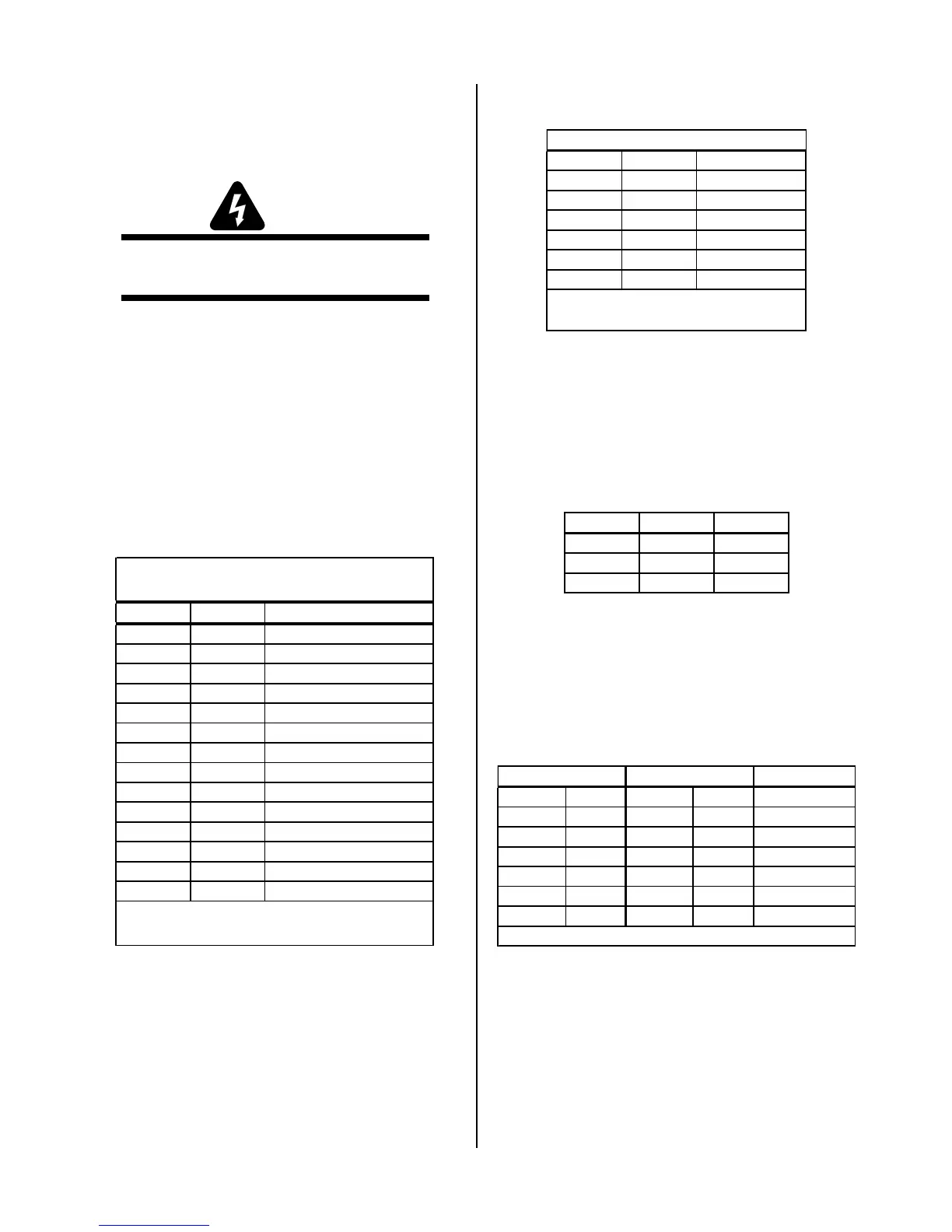
For 400-Volt, 415-Volt, 460-Volt, and 600-Volt Power
Supplies:
Meter + Meter - Indication
E15 E1 Diode Drop
E1 E15 Open
E15 E2 Diode Drop
E2 E15 Open
E15 E3 Diode Drop
E3 E15 Open
E7 E1 Open
E1 E7 Diode Drop
E7 E2 Open
E2 E7 Diode Drop
E7 E3 Open
E3 E7 Diode Drop
E7 E15 Open
E15 E7 Diode Drop*
400V, 415V, 460V, and 600V
Input Diode Indications
* Indication can be twice
other indications.
For 208/230-Volt Power Supplies:
Meter (+) Meter (-) Indication
E7 E1 Open
E1 E7 Diode Drop
E15 E1 Diode Drop
E1 E15 Open
E15 E7 Diode Drop *
E7 E15 Open
208/230V Input Diode PCB
* Indication can be twice
other indications.
c. The meter should indicate a diode drop in one di-
rection and an open in the other direction for each
check. Replace the Input Diode Module Board if
the readings do not match the chart.
d. If Input Diode Module Board is shorted, make the
following checks with an ohmmeter at the Main
Contactor (W1):
Meter (+) Meter (-) Indication
L1 T1 Open
L2 T2 Open
L3 T3 Open
If any test has resistance, then replace the Main Con-
tactor.
2. Output Diode Module Board Circuit Test
a. Use an ohmmeter set on the diode function and
make the following measurements on the Output
Diode Module Boards to Power Output PC Board.
Indication
Meter + Meter - Meter + Meter -
E37 E58 E36 E57 Diode Drop *
E58 E37 E57 E36 Open
E37 E47 E36 E49 Diode Drop
E47 E37 E49 E36 Open
E58 E47 E57 E49 Open
E47 E58 E49 E57 Diode Drop
Output Diode A Output Diode B
* Indication can be twice other indications.
b. The meter should indicate a diode drop in one di-
rection and an open in the other direction for each
check. Replace the Output Diode Module Board(s)
if the readings do not match the chart.