Manual 0-2957 4-17 TROUBLESHOOTING
3. IGBT Module Board Circuit Test
a. Use an ohmmeter set on the diode function and
make the following measurements on the IGBT
Module Board(s) to the Main PC Board.
Indication
Meter + Meter - Meter + Meter -
E10 E4 E27 E23 Diode Drop
E4 E10 E23 E27 Open
E10 E20 E27 E30 Open
E20 E10 E30 E27 Diode Drop
E4 E20 E23 E30 Open
E20 E4 E30 E23 Diode Drop *
IGBT PCB A IGBT PCB B
* Indication can be twice other indications.
b. The meter should indicate a diode drop in one di-
rection and an open in the other direction for each
check. Replace IGBT Module Board(s) if readings
are not the same as the chart.
D. Main Input Power Test
WARNING
The following tests must be performed with the
power supply connected to primary input power.
There are extremely dangerous voltage and power
levels present inside this unit. Do not attempt to
diagnose or repair without proper training in power
electronics measurement and troubleshooting tech-
niques.
Reconnect power and observe proper start-up procedure.
AC indicator on the Front Panel should be ON. If
indicator is OFF there is no voltage to the Power Supply or
an overvoltage condition exists.
1. If AC indicator on Front Panel is OFF, check
for proper AC input voltage between input cables
on the Main Contactor. Input voltage should be as
shown in the following chart. If not, check for
proper voltage at the main power source.
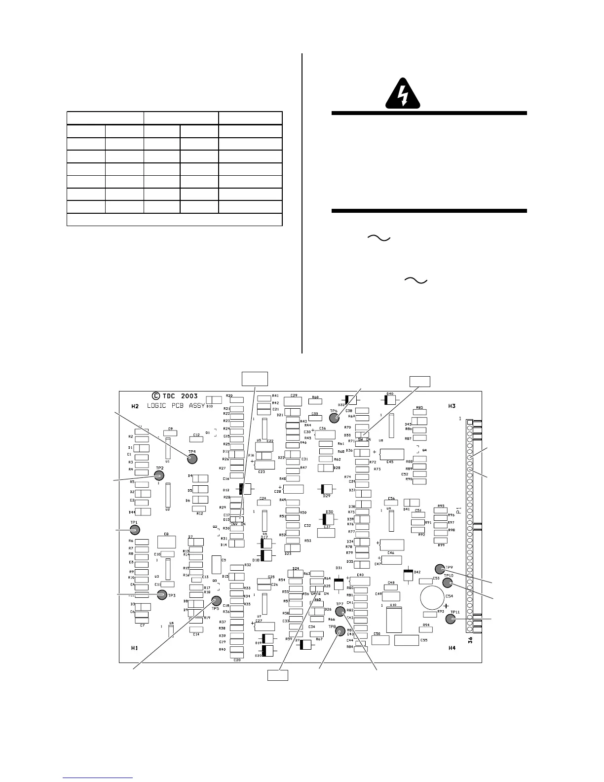
TP9
TP10
TP11
TP3
TP7
TP8
TP5
TP1
TP2
TP4
D13
TP6
Art # A-03654
D25
D33
P1-7
P1-9
Logic Board Layout