A40i, A60i
APPENDIX Manual 0-5466
A-2
1 or 3
f
f
1
2
Hermosillo, Sonora, Mexico
Made in Mexico
Model:
U1
1
1
1max 1e
I
I
U
2
3Ø
3Ø1Ø
1Ø
S/N
U
0
=
X
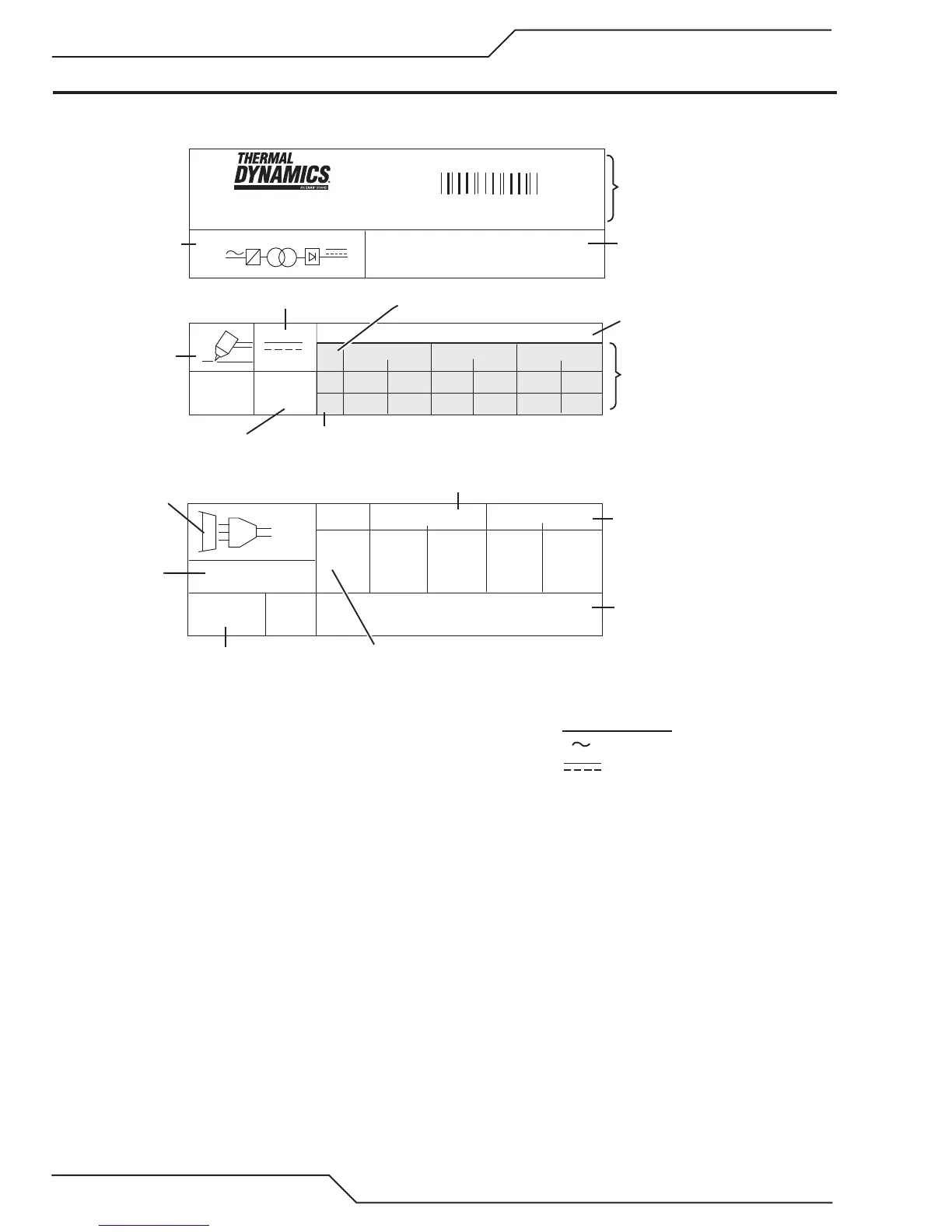
Standard Symbols
Ø
AC
DC
Phase
NOTES:
1. Symbol shown indicates single- or three-phase AC input,
static frequency converter-transformer-rectifier, DC output.
2. Indicates input voltages for this power supply. Most power
supplies carry a label on the bottom of the unit showing input
voltage requirements for the power supply as built.
3. Top row: Duty cycle values.
Duty cycle values meet or exceed the
IEC specified rating.
Second row: Rated cutting current values.
Third row: Conventional load voltage values.
4. Sections of the Data Tag may be applied to separate areas
of the power supply.
I
Art # A-13265_AB
Date of Mfr:
Output Range (Amperage/
Voltage)
Type of Power
Supply (Note 1)
Output Current Type
Rated No-
Load Voltage
Plasma Cutting
Symbol
Manufacturer's Name and/or
Logo, Location, Model and
Revision Level, Serial Number
and Production Code
Conventional
Load Voltage
Regulatory Standard Covering
This Type of Power Supply
Duty Cycle Data (Note 3)
Duty Cycle Factor
Input Power
Specifications
(Phase, AC or DC
Hertz Rating)
Input Power
Symbol
Rated Supply
Voltage (Note 2)
Rated Maximum
Supply Current
Maximum Eective
Supply Current
Degree of Protection
Manufacturer's Electrical
Schematic File Number
and Revision Level
APPENDIX 2: DATA TAG INFORMATION