A40i, A60i
INSTALLATION Manual 0-5466
3-2
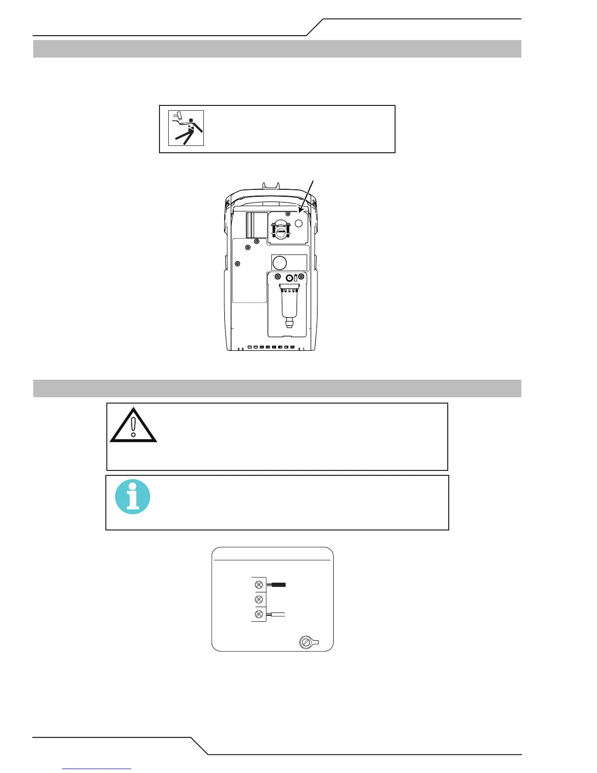
3.04 Opening the Main Switch Cover
Systems are configured for and come with power cord connected for single phase configuration. The input power
switch is located on the rear panel along the top. To access the input locations, remove the screw at the top of the
cover and flip down.
CAUTION
Disconnect power before removing
the cover.
Main Switch Cover
3.05 Primary Input Power Connections
!
CAUTION
The primary power source, fuse, and any extension cords used
must conform to local electrical code and the recommended
circuit protection and wiring requirements as specied in Sec-
tion 2.
NOTE!
As long as the power supply is connected to input power rang-
ing from 208 VAC to 480 VAC, the system will automatically
detect this and run accordingly.
Line
GND
Single-Phase (1ø)
Power Cord
Power Switch
Single Phase Input Power Wiring