A40i, A60i
Manual 0-5466 OPERATION
4T-3
Shown)
3. Install the replacement Electrode by pushing it
straight into the torch head until it clicks.
4. Install the starter cartridge and desired tip for
the operation into the torch head.
5. Hand tighten the shield cup assembly until it
is seated on the torch head. If resistance is felt
when installing the cup, check the threads before
proceeding.
4T.04 Cut Quality
NOTE!
Cut quality depends heavily on setup
and parameters such as torch stando,
alignment with the workpiece, cutting
speed, gas pressures, and operator
ability.
Cut quality requirements differ depending on applica-
tion. For instance, nitride build - up and bevel angle
may be major factors when the surface will be welded
after cutting. Dross - free cutting is important when fin-
ish cut quality is desired to avoid a secondary cleaning
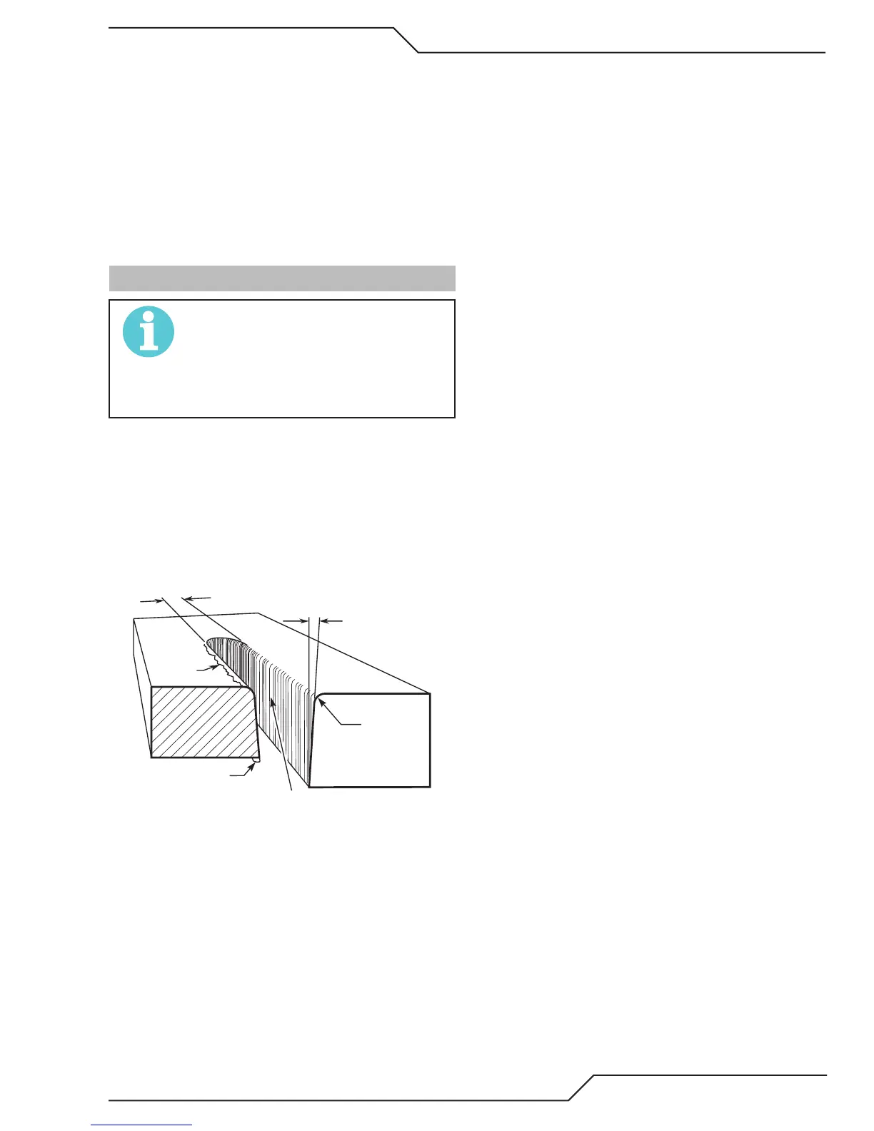
operation. The following cut quality characteristics are
illustrated in the following figure:
Kerf Width
Cut Surface
Bevel Angle
Top Edge
Rounding
Cut Surface
Drag Lines
Dross
Build-Up
Top
Spatter
A-00007
Cut Quality Characteristics
Cut Surface
The desired or specified condition (smooth or rough)
of the face of the cut.
Nitride Build - Up
Nitride deposits can be left on the surface of the cut
when nitrogen is present in the plasma gas stream.
These buildups may create difficulties if the material
is to be welded after the cutting process.
Bevel Angle
The angle between the surface of the cut edge and
a plane perpendicular to the surface of the plate.
A perfectly perpendicular cut would result in a 0°
bevel angle.
Top - Edge Rounding
Rounding on the top edge of a cut due to wearing
from the initial contact of the plasma arc on the
workpiece.
Bottom Dross Buildup
Molten material which is not blown out of the cut
area and resolidifies on the plate. Excessive dross
may require secondary cleanup operations after
cutting.
Kerf Width
The width of the cut (or the width of material re-
moved during the cut).