A40i, A60i
INTRODUCTION Manual 0-5466
2T-2
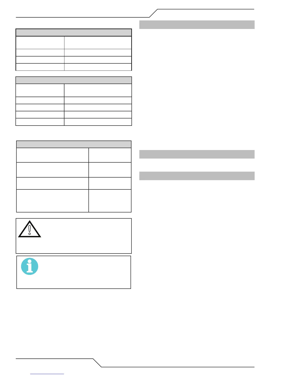
F. Torch Ratings
Automated / Machine Torch Ratings
Ambient
Temperature
104° F
40° C
Duty Cycle 100% @ 100 Amps @ 400 scfh
Maximum Current 120 Amps
Voltage (V
peak
) 500V
Manual Torch Ratings
Ambient
Temperature
104° F
40° C
Duty Cycle 100% @ 60 Amps @ 400 scfh
Maximum Current 60 Amps
Voltage (V
peak
) 500V
Arc Striking Voltage 500V
G. Gas Requirements
Manual and Mechanized Torch Gas Specifications
Gas (Plasma and Secondary)
Compressed Air
Argon
Operating Pressure
Refer to NOTE
90 - 120 psi
6.2 - 8.3 bar
Maximum Input Pressure 125 psi / 8.6 bar
Gas Flow (Cutting and Gouging)
5 - 8.3 SCFM
300 - 500 scfh
142 - 235 lpm
!
WARNING
This Torch is not to be used with
oxygen (O
2
).
The SL60QD torch should not be
used on an HF system.
NOTE!
Operating pressure varies with torch
model, operating amperage, and torch
leads length. Refer to gas pressure settings
charts for each model..
H. Direct Contact Hazard
For standoff tip the recommended standoff is 3/16
inches / 4.7 mm.
2T.04 Quick Connection Torch
The new SL60QD™ (Quick Disconnect) torch allows
for a quick change of the torch handle assembly from
the leads. To change the torch handle assembly do
the following.
1. Remove the torch handle assembly by grasping
the torch handle in one hand and the coupler nut
and leads in the other.
2. Rotate the nut a minimum of one full turn to the
left (counter closkwise) and pull the torch handle
assembly out from the leads in a straight line.
3. To reattach, grasp both as before and carefully
align the internal connecting parts.
4. Carefully press the two together in a straight line.
5. Align the mark on the coupler nut with that on
the top of the torch handle and rotate to the right
(clockwise) drawing the two together and seating
the connections inside.
2T.05 Options And Accessories
For options and accessories, see Section 6.
2T.06 Introduction to Plasma
A. Plasma Gas Flow
Plasma is a gas which has been heated to an ex-
tremely high temperature and ionized so that it
becomes electrically conductive. The plasma arc
cutting and gouging processes use this plasma to
transfer an electrical arc to the workpiece. The metal
to be cut or removed is melted by the heat of the arc
and then blown away.
While the goal of plasma arc cutting is separation of
the material, plasma arc gouging is used to remove
metals to a controlled depth and width.
In a Plasma Cutting Torch a cool gas enters Zone B,
where a pilot arc between the electrode and the torch
tip heats and ionizes the gas. The main cutting arc
then transfers to the workpiece through the column
of plasma gas in Zone C.