A40i, A60i
Manual 0-5466 INSTALLATION
3-7
NOTE!
Filter replacement part numbers can
be found in Section 6 of this manual
Using High Pressure Air Cylinders
When using high pressure air cylinders as the air supply:
1. Refer to the manufacturer’s specifications for installation and maintenance procedures for high pressure
regulators.
2. Examine the cylinder valves to be sure they are clean and free of oil, grease or any foreign material. Briefly
open each cylinder valve to blow out any dust which may be present.
3. The cylinder must be equipped with an adjustable high - pressure regulator capable of outlet pressures up
to 120 psi (8.3 bar) maximum and flows of least 300-500 scfh / 5 - 8.3 CFM (142-235 lpm).
4. Connect supply hose to the cylinder.
NOTE!
Pressure should be set at 120 psi (8.3
bar) at the high pressure cylinder
regulator.
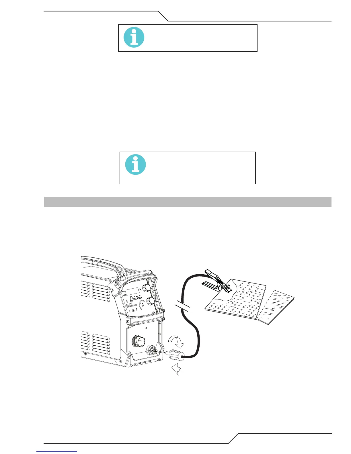
3.08 Work Lead Connections
Connect the Work Lead to the power supply and the work piece.
1. Attache the Dinse type connection of the work lead to the power supply front panel as shown below. Push
in and turn clockwise to the right until tight.
2. Connect the work clamp to the workpiece or cutting table. The area must be free from oil, paint and rust.
Connect only to the main part of the work piece; do not connect to the part to be cut off.
1
2
3
Art# A-13249