Art # A-13280_AC
Art # A-13280_AC
1
1
2
2
3
3
4
4
5
5
6
6
7
7
8
8
9
9
10
10
F F
E E
D D
C C
B B
A A
Rev
Revision
By
Date
Rev
Revision
By
Date
042X1369
C
1 1
10/21/2015
DAT
Victor Technologies Headquarters
16052 Swingley Ridge Road, Suite 300
St Louis, Missouri 63017 USA
Drawn
Date
Sheet
of
Size
Drawing Number
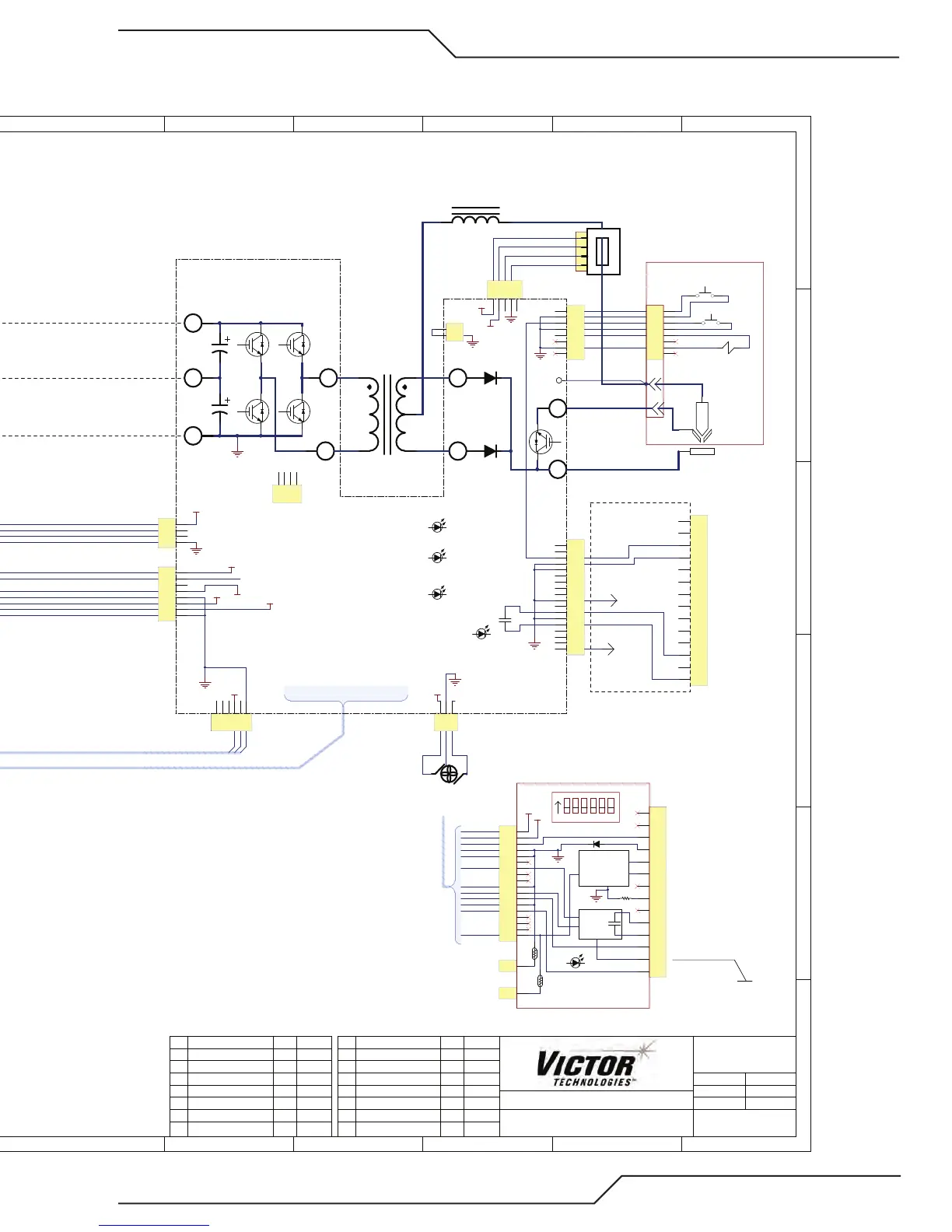
SCHEMATIC
CM60i 208-480VAC, 1 PHASE
The information contained herein is proprietary to Victor Technologies.
Title
Not for release, reproduction or distribution without written consent.
10/6/2017
Date Printed
Date Revised
10/6/2017
AA Production Release DAT 12/07/2016
1
2
3
4
5
6
7
8
9
10
11
12
13
14
J1
ISO_GND
DIVIDED ARV VOLTAGE (-)
DIVIDED ARV VOLTAGE (+)
COMMON
PLATE CONTACT COM
PLATE CONTACT OUT
OK TO MOVE *
OK TO MOVE *
OHMIC
START / STOP (ret)
START / STOP
OHMIC
SENSE
CIRCUITS
ISOLATED
VOLTAGE
DIVIDER
CIRCUITS
+
-
AUTOMATION INTERFACE
PCB (w / OHMIC)
CONTACT
1
2
3
4
5
6
7
8
9
10
11
12
13
14
15
16
17
18
J2
GND
1
2
3
4
5
6
7
8
9
10
11
12
13
14
J1
SW1 ON = Ohmic via TIP
SW2 ON = Collision via TIP
DIVIDER RATIO
START / STOP (ret)
START / STOP
OK TO MOVE *
OK TO MOVE *
-15V
+15V
Work
J401
J602 - 50 PIN RIBBON CABLE
J100 - 50 PIN RIBBON CABLE
AIR IN
FAN1
BASIC CNC
(OPTIONAL)
AUTOMATION INTERFACE (A-SERIES ONLY)
GND
+5V
+15V PRI
GND PRI
+24V
+15V
-15V
GND PRI
6 (G)
1 (+)
2 (-)
0
7 (K)
D300
50 PIN RIBBON CABLE SIGNALS (all others are GND or unused)
PIN NAME (Description) “ /” means signal active low.
1, 3 GATE B, GATE A (Gate drive signals)
5, 6 +15V
7, 9 I_PRI_A, I_PRI_B, (Primary Current Sense signals)
12 /PFC_OFF (Disables PFC)
13 V_SENSE (OutputVoltage signal)
17 I_SENSE (Output Current signal)
19 /OVERTEMP (System over temperature)
20 FAN_ON (Signal turns Fan on)
23 GAS_PWM (Proportional Gas Solenoid drive)
25 /RAR (Rapid Auto Restart Mode)
26 PILOT_SW_O
N ( Signal turns Pilot IGBT on)
28 /PIC ( Tip & Electrode in contact before preflow)
31 /PIP (Torch shield cup is in place)
33 /TRIG_ON (Torch trigger or Start on)
35 SUPPLY_OK ( Input voltage in range and Bias Supply OK)
36 SPARE
37 FAN_FAULT
38 -15V
39 PRESSURE_IN (Reserved for input pressure signal, not used)
40 PRESSURE_OUT (Analog signal gas pressure to the torch)
41 SPARE9_IN (Spare input)
42 I_WORK_SENSE (Work Current Signal)
43 /TORCH_SOL_DETECT (AutomationTorch Sole
noid detected)
45 TOR_SOL_ON (24V PWM drive to automation torch solenoid)
46 /OK_TO_MOVE (turns on OK to Move relay)
48 +3.3V
49 TIP_VOLTS (Signal relative to voltage on tip)
HARNESS TO J609
GND
* MAX 30 V AC/DC @ 1A
INPUT & BIAS SUPPLY PCB
PFC PCB
INVERTER PCB
MULTIFUNCTION DISPLAY & CONTROL PCB
*
DISPLAY_7SEG_QUAD
AC
DC
FAULT
END OF LIFE OVERTEMP
MODE
KNOB -
Rotate to Set Current,
Press to Select Mode
KNOB -
Rotate to Set Pressure
Press to Select Torch
& Lead Lenght
D101
+15V (under knob)
D135
HEARTBEAT (under knob)
D159
PRI _OC (behind PCB)
1
2
3
J102
1
2
3
4
5
6
7
8
9
10
11
12
13
14
15
16
17
18
19
20
J103
GND
J101-J103 Programming
J300 - 1 PHASE
SUPPLY OK
1
2
J304 - HIPOT
+15VPRI / BUS UV
GND
PRESSURE
TORCH
& LEADS
208-480 VAC
+/- 10%
1 Phase.
1
2
3
4
5
6
J101
RED