A40i, A60i
OPERATION Manual 0-5466
4-2
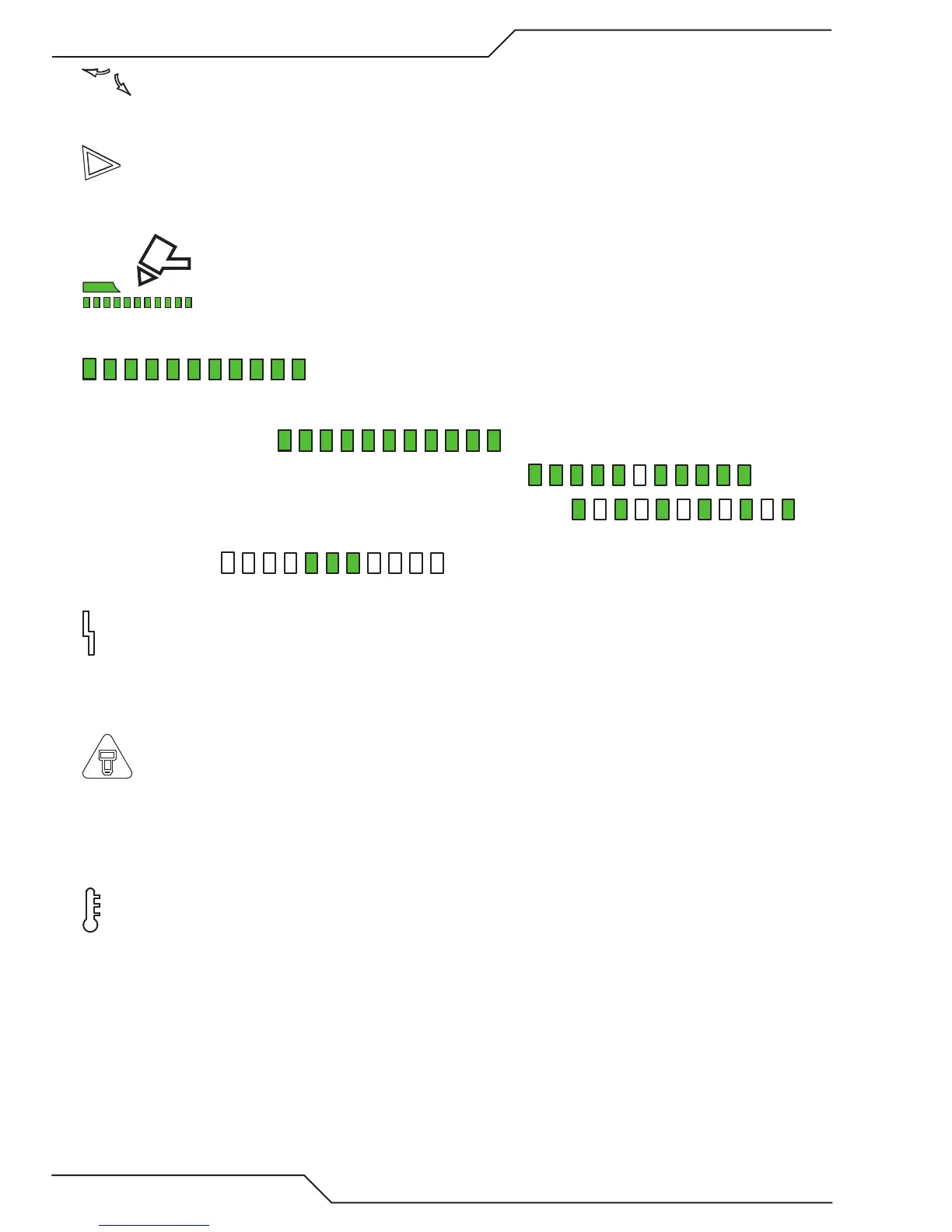
5. Set Mode Indicator
Indicator is ON when unit is owing gas and pressure can be set.
6. Shield Cup In Place Indicator
Indicator is Blinking when any of the following are not in place or connected: Shield Cup, ATC leads or Quick Disconnect.
7. Gouge Mode Indicator
Indicator is ON when unit is in "Gouge" mode and all Cutting Indicators (#8) are illuminated.
8. Type of Cutting Indicator
Dierent segments will be illuminated to indicate dierent types of cutting.
• Gouging - All illuminated
• Normal Cutting and Latch Mode - Center indicator will be off.
• RAR (Rapid Auto Restart) Cutting - Every other indicator will be off.
• Marking - The two indicators to the far right will be off. The Gouge Mode will be selected and gas pressure
set below 20 lbs.
• Set Mode - All indicators will be off.
9. Fault Indicator
Indicator is ON when unit is in fault condition. See error codes appendix for fault light explanations. Flashing when active.
Factory default: O
10. EOL (End Of Life) Indicator
Indicator is normally o. It is also o during Drag Cutting.
When on it is to inform user that consumable failure is imminent
Active and/or operable in all cutting modes except Drag..
11. Over Temp Indicator
Indicator is normally OFF. Indicator is ON/FLASHING when internal temperature exceeds normal limits. Let the unit
cool before continuing operation.