A40i, A60i
OPERATION Manual 0-5466
4T-6
3
4
Art # A-03383
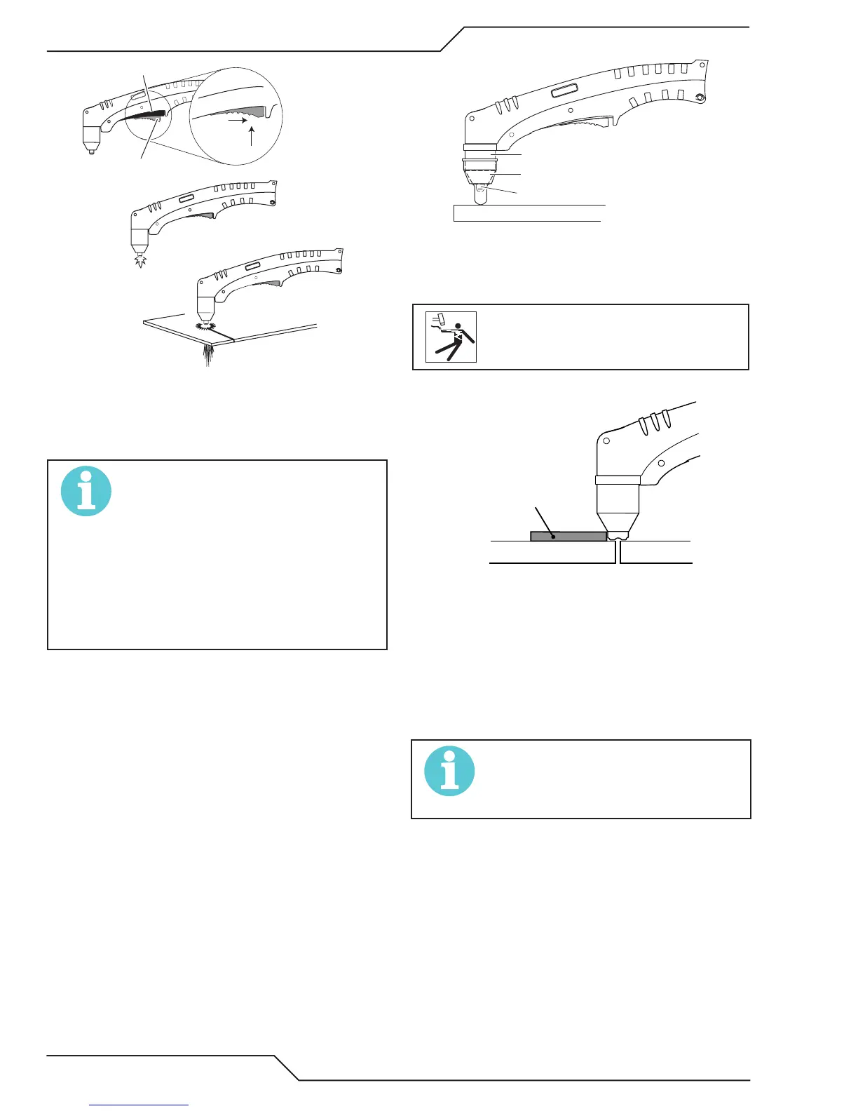
Tr igger
2
1
Tr igger Release
6. Cut as usual. Simply release the trigger assembly
to stop cutting.
7. Follow normal recommended cutting practices as
provided in the power supply operator's manual.
NOTE!
When the shield cup is properly in-
stalled, there is a slight gap between
the shield cup and the torch handle.
Gas vents through this gap as part of
normal operation. Do not attempt to
force the shield cup to close this gap.
Forcing the shield cup against the
torch head or torch handle can dam-
age components.
8. For a consistent standoff height from the work-
piece, install the standoff guide by sliding it onto
the torch shield cup. Install the guide with the
legs at the sides of the shield cup body to main-
tain good visibility of the cutting arc. During
operation, position the legs of the standoff guide
against the workpiece.
Shield Cup
Workpiece
Standoff Guide
Torch Tip
Shield Cup With Straight Edge
The drag shield cup can be used with a non conduc-
tive straight edge to make straight cuts by hand.
WARNING
The straight edge must be non - con-
ductive.
Non-Conductive
Straight Edge
Cutting Guide
Using Drag Shield Cup With Straight Edge
The crown shield cup functions best when cutting
3/16 inch (4.7 mm) solid metal with relatively
smooth surface.
Drag Cutting With a Hand Torch
Drag cutting works best on metal 1/4" (6 mm) thick
or less.
NOTE!
For best performance and parts life, al-
ways use the correct parts for the type
of operation.