cutmaster 102
SERVICE 5-22 Manual 0-4998
3. Using an ohmmeter check continuity between the
following points:
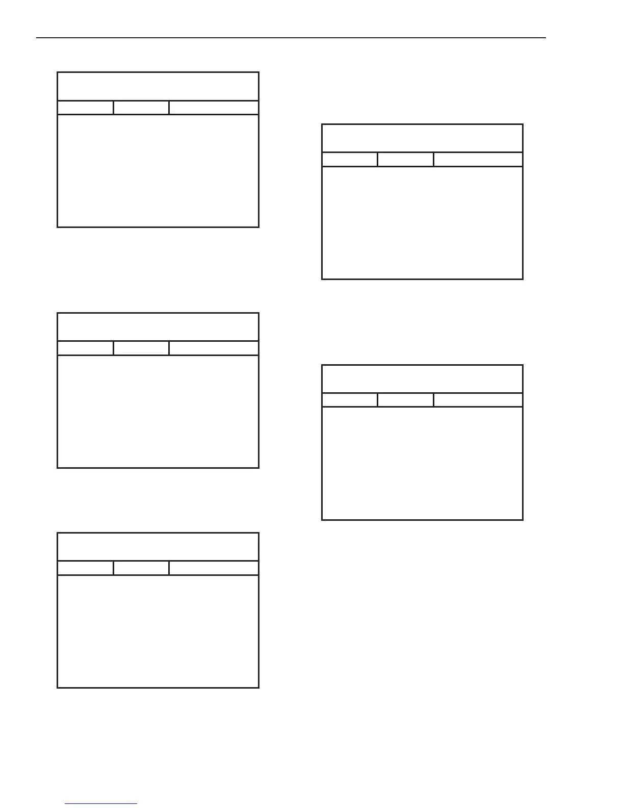
PCB 1 Q2
Test points located on PCB 1* & PCB 2
Meter (+) Meter (-) Indication
PRI 3* MTH 8 Forward Bias
PRI 3* MTH 7 Capacitor Charging
MTH 8 PRI 3* Capacitor Charging
MTH 7 PRI 3* Forward Bias
PRI 4* MTH 8 Forward Bias
PRI 4* MTH 7 Capacitor Charging
MTH 8 PRI 4* Capacitor Charging
MTH 7 PRI 4* Forward Bias
F. PCB 5 IGBT Test
1. Disconnect transformer wires from 40 Amp PCB
5 terminal PRI 1 (A).
2. Using an ohmmeter perform the following
checks:
PCB 5 - Q1
Test points located on PCB 2 AND PCB 5*
Meter (+) Meter (-) Indication
PRI 1* PMTH 1 Forward Bias
PRI 1* PMTH 2 Capacitor Charging
PMTH 1 PRI 1* Capacitor Charging
PMTH 2 PRI 1* Forward Bias
PRI 2* PMTH 1 Forward Bias
PRI 2* PMTH 2 Capacitor Charging
PMTH 1 PRI 2* Capacitor Charging
PMTH 2 PRI 2* Forward Bias
3. Disconnect transformer wire from 40 Amp PCB
5 terminal PRI4 (C).
4 Using an ohmmeter perform the following
checks:
PCB 5 – Q2
Test points located on PCB 2 AND PCB 5*
Meter (+) Meter (-) Indication
PRI 4* PMTH 3 Forward Bias
PRI 4* PMTH 4 Capacitor Charging
PMTH 3 PRI 4* Capacitor Charging
PMTH 4 PRI 4* Forward Bias
PRI 3* PMTH 3 Forward Bias
PRI 3* PMTH 4 Capacitor Charging
PMTH 3 PRI 3* Capacitor Charging
PMTH 4 PRI 3* Forward Bias
G. PCB 1 Output Diode D3 Test
1. Disconnect transformer wires from Main PCB 1
terminal SEC1.
2. Using an ohmmeter perform the following
checks:
PCB 1 D3
(Test points located on PCB 1* & PCB 2)
Meter (+) Meter (-) Indication
CHOKE1 SEC1 Forward Bias
CHOKE1 SEC2 Forward Bias
SEC1 CHOKE1 Reversed Bias
SEC2 CHOKE` Reversed Bias
WORK1 SEC1 Reversed Bias
WORK1 SEC2 Reversed Bias
SEC1 WORK1 Forward Bias
SEC2 WORK1 Forward Bias
H. PCB 5 Output Diode D2 Test
1. Disconnect transformer wires from Main PCB 5
terminal SEC1.
2. Using an ohmmeter perform the following
checks::
PCB 5 – D2
Test points located on PCB 5
Meter (+) Meter (-) Indication
CHOKE1 SEC1 Forward Bias
CHOKE1 SEC2 Forward Bias
SEC1 CHOKE1 Reversed Bias
SEC2 CHOKE1 Reversed Bias
+OUT_1 SEC1 Reversed Bias
+OUT_1 SEC2 Reversed Bias
SEC1 +OUT_1 Forward Bias
SEC2 +OUT_1 Forward Bias
I. PCB 1 Pilot IGBT Test
1. Disconnect wire E35 from Main PCB 1 terminal
TIP1.
2. Using a mutlimeter with a diode test scale, place
the positive probe on PCB 1 terminal TIP1 and
the negative probe on PCB 1 terminal WORK1.
and check for a forward biased diode reading.
3. If the test reveals a failed component, replace
Main PCB 1. If no problem is found, reconnect
wire to Main PCB.